Shenheng Power Equipment Co., Ltd.
- Home
- Products
Products
Since 2001, Shenheng Power has been a trusted manufacturer of power transmission and distribution equipment, delivering reliable electrical solutions globally.

- Solutions
- News & Blog
- Service
- About Us
- Contact Us
Since 2001, Shenheng Power has been a trusted manufacturer of power transmission and distribution equipment, delivering reliable electrical solutions globally.
Buyers evaluating industrial lv switchgear for plant feeders, motor control centers, and reactive-power sections need a clear busbar decision path before the assembly drawing is frozen.
This guide explains how EPC and facility teams align busbar rating, material, bracing, joints, and temperature-rise checks with the approved single-line diagram and fault study. Use it as a procurement checklist—not as a substitute for project-specific engineering approval.
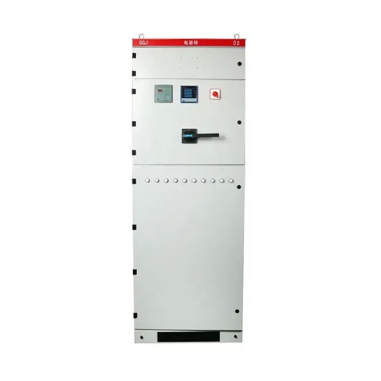
In industrial lv switchgear assemblies, the busbar system carries continuous current and withstands short-circuit forces between the incoming device and outgoing feeders. Undersized bars, weak bracing, or poorly defined joints show up later as overheating, nuisance trips, or delayed factory acceptance.
Treat busbar selection as a design input, not a catalog afterthought. The purchase order should cite measurable values—rated current, short-time withstand, material, plating, joint method, and required temperature-rise evidence—against the approved study.
For plant context on fixed versus withdrawable arrangements, review the GGD vs MNS low voltage switchgear comparison before locking the assembly form.
Lock these inputs before normalizing bids:
| Input | Why it matters | Typical source |
|---|---|---|
| Rated current and diversity | Thermal sizing of main and distribution bars | Load study / feeder list |
| Short-circuit withstand (Icw / Ipk) | Bar cross-section, spacing, and bracing | Fault study |
| Busbar material (Cu / Al) | Conductivity, mass, joint practice, corrosion | Owner standard / RFQ |
| Plating and joint method | Contact resistance and maintenance access | Assembly drawing notes |
| Temperature-rise verification basis | Comparable quotations and FAT scope | IEC 61439 assembly rules |
| Enclosure ventilation / IP | Heat dissipation and derating | Room layout / site data |
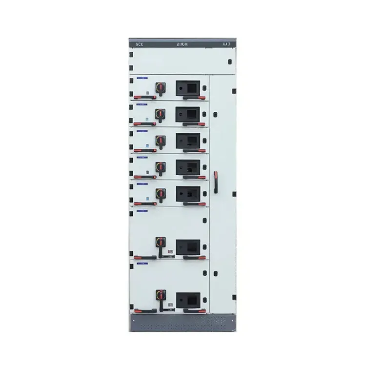
Request outline drawings that show main horizontal bars, vertical risers, droppers, and joint locations early so civil, cable, and protection teams can work in parallel.
Operating context changes acceptable busbar solutions. Continuous high-load feeders often favor copper for thermal margin, while some industrial standards allow aluminum when joint design, plating, and maintenance access are controlled.
Harmonic-rich loads, densely packed compensation sections, and frequent feeder additions increase local heating risk. Record measured ambient temperature, altitude, and ventilation assumptions in every RFQ for industrial lv switchgear projects.
If motor feeders and feeder arrangement dominate the board, coordinate busbar duty with panel layout inputs using the GGD AC distribution cabinet layout tips so cable entry, breaker placement, and bar ratings stay aligned.
| Document / item | Purpose | When to request |
|---|---|---|
| Single-line diagram and feeder schedule | Define continuous and peak bus duties | Before quotation comparison |
| Fault study excerpt | Confirm short-time withstand and bracing | Design phase |
| Busbar material / plating note | Normalize Cu vs Al offers | RFQ release |
| Temperature-rise or type-test evidence | Compare thermal performance basis | Before purchase order |
| GA drawing with joint locations | Cable entry and maintenance planning | Design freeze |
| Torque / assembly procedure | Installation quality control | Before shipment |
Attach this table to RFQs so vendors return comparable technical packages for industrial lv switchgear assemblies.
Installation quality often determines long-term busbar reliability more than small differences in quoted first cost. Confirm torque values, contact surfaces, phase identification, and clearances against the approved drawing before energization.
Before factory acceptance or site energization, plan insulation resistance checks, functional protection tests, and—where the contract requires—thermography baselines on joints after initial loading.
Maintenance access should be designed into the layout: reachable joint covers, spare bar or connector stock for critical feeders, and clear labeling for future feeder additions. Fault-clearing philosophy for the same assembly family is covered in low voltage switchgear fault clearing basics.
For many industrial LV switchgear busbar scopes, Shenheng Power publishes a relevant catalog starting point at industrial LV metal enclosed switchgear.
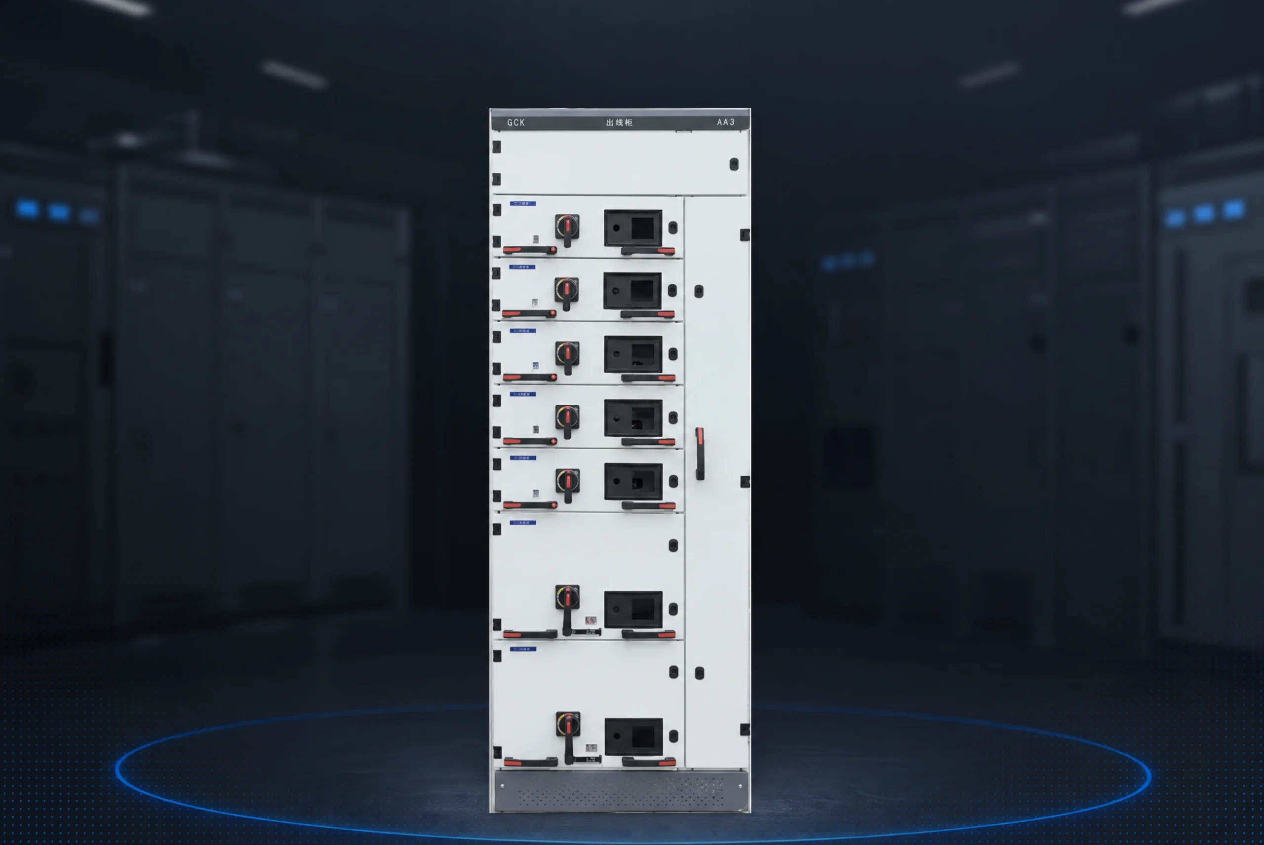
Fit boundary: This recommendation supports typical GGD / GGJ / MNS distribution and industrial scopes documented on the product page. It is not a substitute for project-specific studies when unusual fault levels, altitude extremes, special plating rules, or national utility requirements apply.
If your study points to a different arrangement or rating, review the broader Low Voltage Switchgear category and submit study inputs through Contact Shenheng Power.
Include rated current, diversity assumptions, prospective fault level, material preference, plating/joint method, enclosure conditions, and the temperature-rise or type-test evidence required for comparison.
Choose copper when thermal margin, compact geometry, or owner standards prioritize conductivity. Aluminum can be acceptable when joint design, plating, maintenance access, and derating are documented in the approved design.
Higher short-time and peak currents increase electrodynamic forces. The bracing, spacing, and support arrangement must match the fault study used for the industrial LV switchgear assembly.
Confirm joint method, plating, torque procedure, and the agreed temperature-rise verification basis so factory acceptance compares offers on the same thermal evidence.
Request GA drawings with joint locations, wiring/single-line references, assembly or torque procedures, and the agreed routine or type-test documentation aligned to the purchase order revision.
Re-check whenever load growth, feeder additions, fault-level updates, ambient assumptions, or enclosure ventilation changes after the original study.