2001 yılından bu yana Shenheng Power, güvenilir bir güç iletim ve dağıtım ekipmanları üreticisi olarak küresel çapta güvenilir elektrik çözümleri sunmaktadır.
2001 yılından bu yana Shenheng Power, güvenilir bir güç iletim ve dağıtım ekipmanları üreticisi olarak küresel çapta güvenilir elektrik çözümleri sunmaktadır.
Transformer Core Ground Test Procedure and Diagnosis
Release Time: 2026-10-08
A transformer core ground test checks the insulation between the magnetic core and grounded parts after the intended core grounding connection is isolated through an approved procedure. Its purpose is to investigate an unintended additional ground, not to remove the transformer’s protective tank earth. Results depend on the actual core, frame and grounding design. The test is meaningful only when the measured path is identified and the intended operating connection is correctly restored afterwards.
This guide explains the engineering workflow, report requirements and interpretation limits. It is for maintenance planning and review, not a do-it-yourself connection sequence. A qualified team must use the manufacturer’s drawings, permitted test duty and site isolation procedure.
Why the core grounding arrangement matters
A transformer core is assembled from magnetic steel laminations and is surrounded by other structural and insulation components. The intended grounding arrangement controls its electrical potential. An unintended additional connection can create an unwanted current path and may contribute to heating or other abnormal behavior, depending on the design and location.
The familiar phrase “single-point core ground” is useful, but it must not replace the actual drawing. Some equipment provides separately identified core and frame connections or other arrangements that require different measurements. Determine what each terminal represents before deciding that every ground visible near the tank is a core ground.
The Bureau of Reclamation transformer diagnostics manual provides public background on intentional and unintentional core grounds. Use that explanation to frame the investigation; the asset’s documentation establishes how the actual connections can be isolated, tested and restored.
Distinguish core ground, frame ground and tank earth
The magnetic core, its supporting frame and the external tank are different parts of the equipment. A drawing may show separate leads or internal connections for them. A measurement that includes several paths can be difficult to interpret if the report labels it only “core test.”
Protective tank grounding is not the removable diagnostic connection discussed here. Confusing the two can create an unsafe work arrangement and invalidate the measurement. The work plan should name the intended core connection and preserve the required protective grounding of the asset and test environment.
If the transformer does not provide an accessible core ground lead, the investigation may require manufacturer involvement or a different diagnostic approach. Do not create a test terminal or open an oil-filled tank merely to follow a generic checklist. Access constraints should be a recorded limitation, with an agreed next step.
For the broader insulation context, see the transformer insulation resistance guide. A winding insulation measurement and a core-to-ground assessment are different tests; their results should not be mixed in one acceptance column.
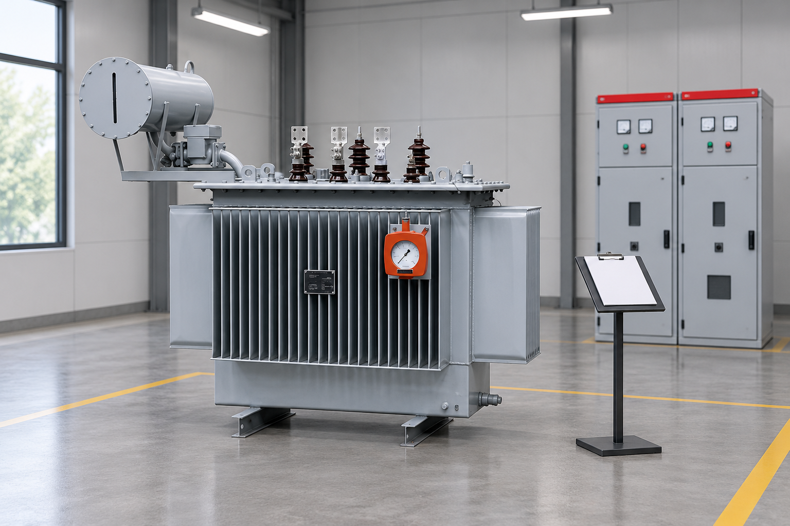
Define the manufacturer-approved measurement path before the outage. Reference-based illustration.
Define the test boundary before the outage
Collect the latest drawing, nameplate identity, maintenance history and any previous core or frame test report. Verify that the drawing matches the installed transformer rather than a similar model. Identify the exact terminal, intentional connection, measured path and normal operating configuration.
Agree the test method and permitted duty with the manufacturer or responsible specialist. The approved procedure should define the instrument, test voltage, duration, temperature information and discharge requirements appropriate to the insulation involved. A winding’s rated voltage does not establish a safe core-insulation test voltage.
The test plan should also define what a result could answer. For example, it may distinguish a suspect unintended ground from an external connection problem, or establish a commissioning baseline after transport. State any limitations that prevent an internal location from being determined by this measurement alone.
A controlled procedure has five review stages
First, establish the work boundary. The qualified team identifies every relevant source, confirms the required isolation and applies the site controls. Stored energy, induced voltage and neighboring equipment are part of that assessment. The US electrical power safety provisions are a reference where applicable; local requirements and the approved site procedure control the job.
Second, document the starting configuration. Record the intended core and frame connections with terminal identities and photographs. This establishes what must be restored and reduces the chance that a later reviewer interprets a test made through an unidentified parallel path.
Third, establish the manufacturer-approved diagnostic configuration. Only the designated connection is isolated as permitted by that procedure. The report should show which insulation path the instrument measures. It should not describe simply “ground removed,” because that wording leaves a critical ambiguity.
Fourth, perform and record the approved measurement. Preserve the raw result, instrument details, test conditions and any abnormal behavior. Do not escalate test voltage or repeat a test indefinitely to obtain a preferred value. Unexpected observations should trigger the agreed technical review.
Fifth, complete discharge and restoration through the authorized procedure. Reconnect the intended arrangement, verify it and record the final condition. The test is incomplete until the asset is demonstrably returned to its documented operating configuration.
Interpret a low reading without jumping to a fault location
A low measured resistance may indicate an unintended connection, but first confirm that the intended connection was actually isolated and that the correct path was measured. A remaining external connection, contaminated terminal, test setup issue or misunderstood drawing can produce a misleading result.
If the setup is valid, the measurement can support an investigation of unintended grounding. It does not necessarily locate the internal contact or establish how much heating occurred. The specialist should consider additional evidence, asset design and the consequences of invasive work before specifying a repair.
A high reading also has limits. It applies to the measured path under the documented test conditions. It does not establish that every internal defect is absent, and it cannot compensate for a failed restoration check. Preserve both the result and the description of its scope.
Evidence and decision table
The table below helps the reviewer separate a measurement problem from an asset problem. Numerical acceptance values must come from the applicable equipment guidance and agreed procedure.
Finding
First verification
Additional evidence
Recorded outcome
Low core-to-ground resistance
Correct terminal and intended connection isolated
Drawing, connection photograph and raw instrument result
Valid abnormal result or corrected test boundary
Low value only in one configuration
Which parallel paths were included?
Core and frame arrangement, external wiring
Explain the path difference before diagnosis
Change from historical baseline
Same method and conditions?
Previous voltage, duration, temperature and instrument
Comparable trend or qualified comparison
No accessible core terminal
Is an approved alternative available?
Manufacturer instructions and design drawing
Record limitation and specialist action
Normal measurement but abnormal gas trend
Are the tests addressing the same hypothesis?
DGA history and event records
Continue targeted investigation where warranted
Uncertain final connection
Restoration not independently verified
Signed final configuration check
Hold release until the authorized check is complete
Combine the result with transformer condition evidence
An unintended core ground can be investigated alongside evidence of heating or a change in transformer behavior. The dissolved gas analysis guide explains how to organize oil gas trends and operating context. DGA can support a thermal hypothesis, but it cannot uniquely identify an additional core ground.
The excitation current test provides another view of transformer behavior under its own test conditions. Select additional tests because they answer a defined question. A bundle of unrelated favorable results should not be used to dismiss an unexplained abnormal core measurement.
Review recent transport, installation, repair, internal access and electrical events. These dates can help explain when a change became apparent. Distinguish chronology from causation: a problem noticed after transport is not automatically proven to have been caused by transport.
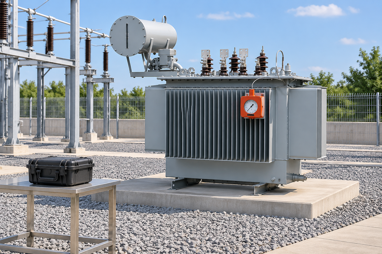
Verify restoration of the intended grounding arrangement. Reference-based illustration.
What a useful test report includes
The report should identify the transformer, core and frame arrangement, drawing revision, measurement path, test method, instrument, conditions and result. Include the starting and final connection records. State the assessment basis rather than reporting a generic pass label with no reference.
If the result is abnormal, separate the observation from the suspected cause. List the verification already completed, unresolved alternatives and proposed next action. Assign responsibility and a completion time. If a decision is deferred, identify who has authority over the equipment’s operating state in the meantime.
For an accepted commissioning baseline, store the report with the final installed configuration. Retain it when the asset moves or undergoes maintenance. A future measurement becomes much more useful when the reviewer can establish that the comparison involves the same insulation path.
Procurement questions that prevent later uncertainty
Ask whether the offered transformer provides an accessible identified core ground, how the frame is treated and what diagnostic documentation will be supplied. Request the permitted test procedure and relevant baseline records. These are configuration questions, not features that should be inferred from a photograph.
The 35 kV oil-immersed transformer product page provides a starting point for discussing the project. Confirm the actual design, accessibility and maintenance requirements in writing. The exterior illustration in this article does not show internal core construction or prove the presence of an accessible test connection.
During handover, ask the supplier and commissioning team to reconcile the terminal labels, drawings and final connection photographs. Resolve discrepancies before accepting the documentation package. A correctly executed test can still become unusable as a baseline if the report refers to an outdated drawing or an unidentified lead. Keep the manufacturer correspondence that explains any unusual arrangement, so a later maintenance team can distinguish a deliberate design feature from an unauthorized field modification.
Learn the core’s role before reviewing its grounding
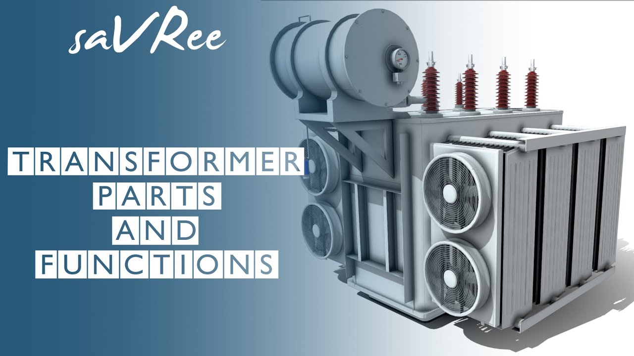
The educational explanation below introduces the transformer core and other major parts. It provides construction context; the grounding test still requires the actual manufacturer’s method and qualified personnel.
Further learning: Transformer Parts and Functions — saVRee. This educational video supports the topic; it is not a product demonstration or an operating authorization. Videoyu YouTube'da aç.
Sık sorulan sorular
Is a core ground test the same as testing the tank earth?
No. The diagnostic assessment concerns the magnetic core’s intended grounding arrangement and insulation path. The protective tank earth is a different connection and must not be confused with the designated diagnostic lead.
Does a low core insulation reading prove an internal fault?
It requires investigation. First verify the drawing, terminal identity, isolated intended connection and measurement setup. A valid abnormal result may support an unintended-ground diagnosis, but does not necessarily locate the contact.
Can the winding voltage rating determine the core test voltage?
No. The permitted duty must come from the actual core insulation design and manufacturer-approved procedure. A winding rating is not a substitute for that information.
Why is the restoration check part of the test result?
The diagnostic configuration can differ from the operating configuration. Correct restoration and verification of the intended grounding arrangement are required before the authorized return to service.
Shenheng Elektrik, müşterilerinin güvenli, verimli ve sürdürülebilir güç yönetimi elde etmesini sağlayarak, güç ekipmanı çözümlerinde küresel bir lider olmayı taahhüt eder.

 Shenheng Elektrik Ekipmanları Ticaret Limited Şirketi.