Substation insulation coordination selects equipment withstand levels and protective measures against the overvoltages expected in the actual network. It connects the system’s highest operating conditions, temporary overvoltages, lightning and switching exposure with the insulation characteristics of transformers, switchgear, cables and other equipment. The objective is a technically justified and economical arrangement, not simply the highest available insulation rating. A complete assessment includes surge arresters, connection geometry, environmental conditions and equipment interfaces. Human safety, operating access and protective grounding remain separate requirements that must also be satisfied.
Begin with the network rather than a catalog value
Identify the system voltage, highest voltage for equipment, frequency, grounding arrangement and supply configuration. Include normal and alternative operating states. Record incoming overhead lines, cables, transformer connections and switching devices that may influence overvoltage exposure.
List the equipment insulation characteristics and their applicable test basis. Do not assume that two devices with the same nominal voltage have identical impulse withstand requirements. The specified framework, equipment standard and installation conditions matter when selecting and comparing ratings.
ใช้ substation single-line diagram guide to organize the network boundaries. Combine that drawing with the physical layout and cable information. The electrical connections and installed distances must both be understood before evaluating the exposure at an equipment terminal.
Coordinate incoming circuits, arresters and equipment interface data. Reference-based illustration.
Main terms and the questions they answer
Term or input
What it describes
ทำไมจึงสำคัญ
Procurement check
Highest voltage for equipment
Voltage class used in equipment coordination
Nominal system voltage alone is incomplete
Confirm the project value and equipment selection
Rated withstand voltage
Specified insulation capability under defined tests
Equipment must suit the assessed exposure
Identify test type, standard and report
Temporary overvoltage
Elevated voltage lasting longer than an impulse event
Grounding and network events affect equipment and arresters
State magnitude-duration assessment
Lightning exposure
Fast surge conditions associated with lightning paths
Incoming circuits and layout influence protection
Connect shielding and arrester studies
Switching exposure
Overvoltages associated with switching events
Device and network combinations can matter
Identify relevant switching cases
Protective arrangement
Measures intended to reduce equipment exposure
Installed geometry affects the result
Verify rating, location and connections
This is a qualitative terminology table. IEC 60071-1 addresses selection principles for rated withstand voltages in its stated scope. IEC 60071-2 provides application guidance. Their public descriptions do not replace the full project method, and insulation coordination is not a substitute for human-safety design.
Distinguish types of overvoltage
Temporary overvoltages and fast impulse events impose different duties. An assessment should describe the relevant event, its duration or waveform assumptions, and where it is evaluated. A single “surge voltage” figure without that context is not a useful specification.
Ground faults, load rejection or other network behavior may influence temporary overvoltage conditions. Lightning can enter through incoming circuits or interact with the physical site arrangement. Switching events may involve breakers, transformers, cables or other equipment combinations. The designer should identify which events are relevant rather than list every possible phenomenon without analysis.
Avoid transferring an overvoltage result from a different substation merely because its nominal voltage matches. Source characteristics, grounding, cable lengths and equipment can differ. If a screening assessment is used, state its assumptions and the conditions that require a more detailed study.
Match equipment withstand characteristics
Request the actual insulation ratings for each equipment category. Identify phase-to-earth, phase-to-phase and relevant longitudinal insulation as required by the design. Keep the equipment standards and test methods attached to those values so the comparison remains meaningful.
Do not treat a larger impulse number as proof of complete suitability. The thermal, current, fault and environmental duties remain necessary. A more expensive insulation option may provide little benefit if the main issue is an inappropriate arrester or a poorly routed connection.
Review interfaces carefully. A transformer, termination and cable can each have appropriate individual documentation yet form a problematic connection if the installed arrangement differs from their assumptions. Confirm connector type, screen treatment, clearances and the environment at the joint through coordinated drawings.
Select arresters with temporary-overvoltage duty in view
An arrester must remain suitable for the network operating and temporary-overvoltage conditions while providing the intended protective behavior. Its rating cannot be selected from nominal voltage alone. Grounding arrangement and expected events need to be included in the evaluation.
Ask the designer to identify the arrester characteristics used, the protected equipment and the assumed duty. Compare the protection level with the equipment withstand through the adopted method. The resulting margin belongs to the project and should not be replaced by an unqualified generic percentage.
ใช้ substation grounding-system guide to organize the site bonding and current-path questions. It complements insulation coordination by identifying installation interfaces, while the coordination study explains how protective devices and insulation fit together.
Installed distance and leads influence protection
The equipment does not experience an arrester data sheet in isolation. Connections between the arrester, protected terminal and grounding system influence the installed response. Layout changes can therefore matter even when the same catalog model is retained.
Review line and earth lead routing, supports, clearances and the separation from protected equipment. Include cable transitions and incoming circuits in the physical model. Do not accept a site relocation without checking the assumptions behind the protective arrangement.
Require photographs and as-built dimensions for critical interfaces. If an installation contractor chooses a different route to avoid an obstruction, the engineering review should decide whether the change is acceptable before completion. An accurate drawing is part of the protection evidence, not merely a record for future construction.
Verify that installation geometry matches the approved study. Reference-based illustration.
Environmental and site conditions
Altitude, contamination, humidity and other environmental conditions can influence insulation and installation requirements. Identify the site’s special conditions and the relevant equipment instructions. Do not apply one generic correction factor to every component without checking the applicable method and design.
For outdoor equipment, review weather exposure and the condition of external insulation. For indoor equipment, consider condensation and pollution rather than assuming that a roof creates a benign environment. The complete assembly includes exposed interfaces, housing and the cable system.
The lightning protection design guide addresses the direct-strike and site-current-path questions. Keep that work connected to insulation coordination while preserving their distinct functions. A shielding assessment does not independently establish the withstand level of every electrical interface.
When a detailed simulation may be needed
A basic standards-based selection can be appropriate where the network and equipment fall within a well-understood application. More complex arrangements or uncertain exposure may require a detailed transient study. The designer should identify the decision basis and the input data required.
Possible concerns include unusual cable arrangements, switching behavior, weak or changing sources, or equipment sensitivity that is not captured by a simple comparison. These conditions are prompts for review, not proof that every project needs the same simulation. Use engineering judgment and the owner’s requirements to define the scope.
A study report should describe the model, operating cases, assumptions, equipment characteristics and sensitivity to uncertain inputs. A plotted waveform without those details is difficult to audit. Ask the reviewer to explain which conclusions are robust and which depend on information that must be confirmed before procurement.
Integrate a packaged substation into the site
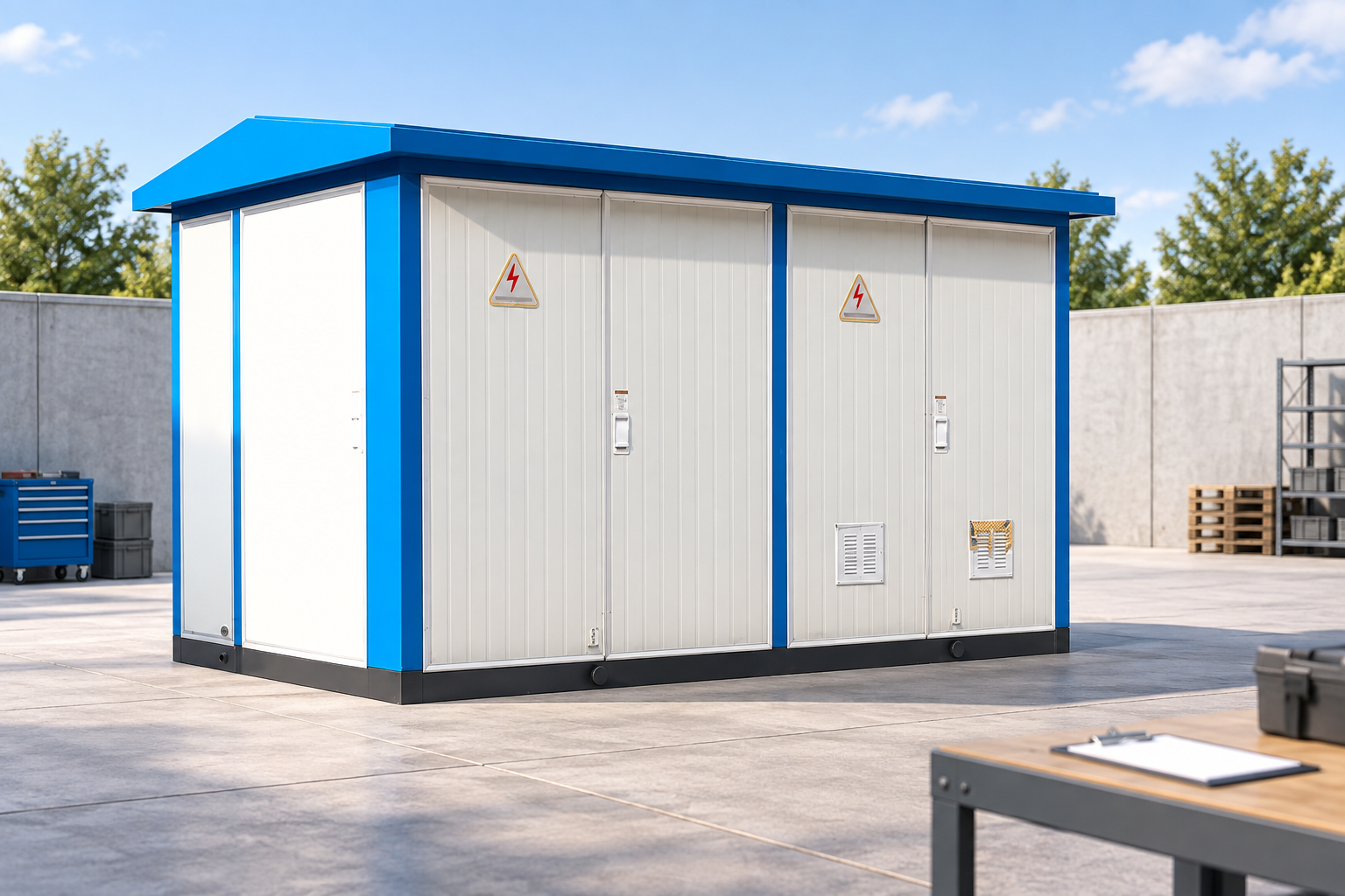
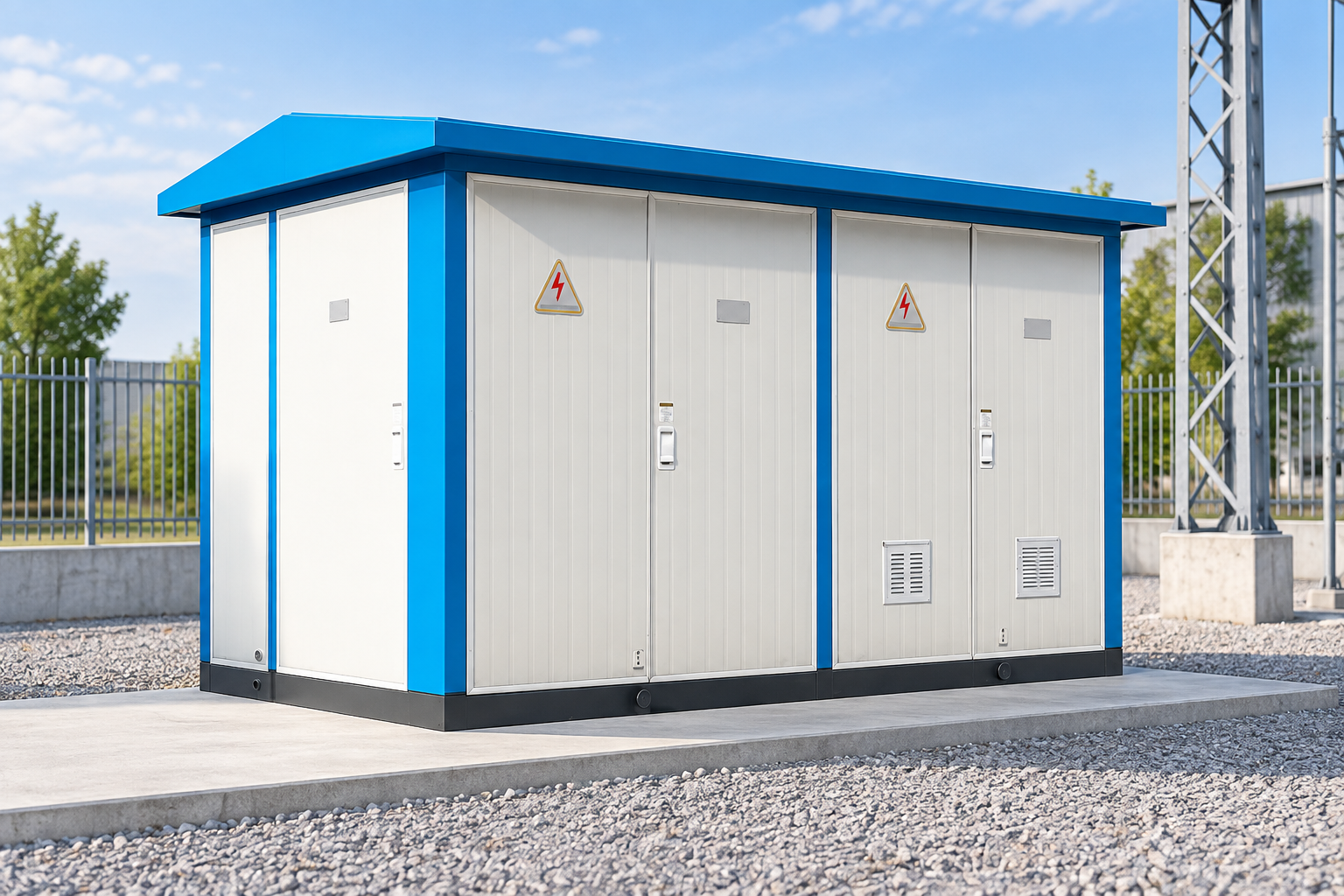
The website’s compact outdoor substation is a relevant equipment category for coordination questions. Its enclosure and factory assembly do not establish the incoming-circuit exposure or the final site grounding arrangement.
Clarify what is included in the supplier’s package and what the site designer must provide. Request equipment insulation data, arrester information if supplied, cable interface requirements and installation limits. Identify any external protective measures assumed by the factory design.
The project must reconcile those assumptions with the actual site. A factory test report and a site study answer related but different questions: the former describes equipment evidence, while the latter evaluates its application. Acceptance should confirm that both refer to the delivered configuration and installed interfaces.
Procurement and commissioning record
Provide bidders with the required equipment voltage class, withstand framework, source conditions, grounding information, environment and relevant transient-study requirements. Ask for deviations, report identifiers and the exact configuration covered by the evidence. Do not leave essential selection values to an unexplained “standard design” statement.
At commissioning, verify equipment labels, arrester types and connection routes against the approved package. Check termination installation, bonding and visible condition through the qualified inspection program. Retain the final drawings, test records and any approved changes in one coordinated file.
Review the assessment when the network changes. New sources, altered grounding, longer cables or moved protective devices can affect the original assumptions. An equipment replacement should trigger a comparison of the relevant insulation and interface characteristics rather than an automatic like-for-like acceptance based only on nominal voltage.
Further learning
Further learning: Insulation Co-ordination in Power System Engineering |High Voltage Engineering Lecture Series |BIL — Simplified EEE Studies. This educational video supports the topic; it is not a product demonstration or an operating authorization. เปิดวิดีโอบนยูทูป.
คำถามที่มักถูกถาม
Is insulation coordination the same as choosing BIL?
No. Selecting an impulse withstand value is one element. The complete task evaluates expected overvoltages, protection, environmental conditions and equipment interfaces using the adopted framework.
Does a higher withstand rating always improve the project?
It may increase margin in a particular assessment, but it does not resolve every interface or protection problem. Select an economical validated arrangement that meets the actual duty.
Does the IEC insulation-coordination framework cover human safety?
Its public scope distinguishes insulation coordination from human-safety requirements. Access, electrical clearances for personnel, isolation and grounding must be addressed separately through applicable rules.
When should the study be reviewed?
Review material changes to sources, grounding, cable arrangement, equipment insulation or protective-device locations. Confirm that the final installed arrangement still matches the assumptions.

 บริษัท เสินเฮิง พาวเวอร์ อีควิปเมนท์ จำกัด.