
 บริษัท เสินเฮิง พาวเวอร์ อีควิปเมนท์ จำกัด.



A circuit breaker anti-pumping circuit prevents repeated closing when a close command remains present while the breaker operates or trips. It coordinates the close coil, auxiliary contacts, trip logic, interlocks, local or remote selector and control voltage. The circuit must be checked as part of the complete switchgear control scheme, not as an isolated relay symbol.
Anti-pumping control purpose
An anti-pumping circuit prevents repeated breaker closing when a close command remains present while the breaker is operating or trips. The circuit should allow a new close command only after the prior command is removed and the correct permissives are restored.
Review close coil, auxiliary contacts, trip logic, anti-pumping relay, local or remote selector, interlocks and control voltage. Test sustained close, trip during close, repeated commands and loss of control power under an approved safe method.
Distinguish anti-pumping from permissives and reclosing
Anti-pumping addresses a specific control problem: a maintained close command should not cause repeated closing attempts when the breaker opens and the command remains present. It is separate from the permissives that determine whether closing is allowed in the first place. A truck-position interlock, earthing-switch interlock or protection lockout may block closing, but those functions do not by themselves establish anti-pumping behavior. Review the complete manufacturer’s circuit, including auxiliary contacts, closing coil and the reset condition, before identifying which component performs the function.
Trace the logic through distinct states on the approved drawing. Start with the breaker open and a valid close request. Follow the closing-coil supply and the contact changes when the mechanism operates. Then retain the close request while introducing the relevant approved trip condition in a safe test arrangement. Determine why another close attempt remains blocked and what must change before a subsequent deliberate close request is accepted. The exact relay designation and contact sequence vary between designs; do not transfer a generic wiring sketch directly to an installed panel.
Check local and remote command paths separately. An anti-pumping function that works through the local pushbutton may be bypassed by an incorrectly integrated remote output. Review whether the supervisory system sends a pulse or maintains an output, how intermediate relays behave and what happens after loss and restoration of control power. The protection trip path must retain its intended authority. Automatic reclosing is a separate protection scheme with its own approved sequence and blocking conditions. Anti-pumping should not be disabled merely to make a remote command or reclosing test appear successful.
Record an acceptance sequence rather than only a statement that the breaker opened and closed. Include initial state, control source, request duration, trip input, observed mechanism response, coil behavior and reset action. Test arrangements must follow the manufacturer’s instructions and site electrical-safety procedure; avoid holding a coil energized beyond its allowed duty. If behavior differs from the drawing, inspect configuration, contact identification and wiring under safe isolation. Do not compensate by changing interlocks or extending command duration without an approved design review. The final circuit record should make sustained-command behavior reproducible for later maintenance.
Understand the maintained-command problem
A close command can remain present longer than intended because a switch is held, an output remains asserted or a control fault occurs. If a breaker closes and then trips while that command is still present, repeated closing attempts can expose the mechanism and power system to an unwanted operating sequence. Anti-pumping addresses this maintained-command condition through the breaker’s actual control design.
The designer should state the intended behavior before discussing relay symbols. A released-and-renewed command may be needed before another close attempt becomes available, but the exact reset behavior depends on the implemented scheme. Do not identify an unlabeled contact on a generic internet diagram and assume that every manufacturer’s breaker uses it in the same way.
Trace the approved close-command path
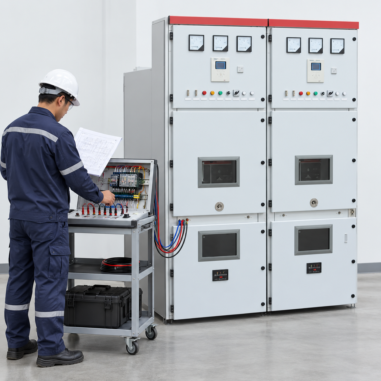
Review the released control drawing and identify the close request, close coil, relevant auxiliary contacts, anti-pumping function and any permissive contacts. Establish which parts are internal to the breaker and which belong to the switchgear panel or protection scheme. The factory and site documents must describe the same equipment revision.
Local and remote commands may share a final close path or use different upstream logic. A local command that behaves correctly does not automatically prove the remote path. Record the selector positions and command priorities relevant to each test. The review should also identify the source and rating of the control supply rather than assuming that a nominal panel voltage proves every coil and interface is compatible.
Separate anti-pumping from trip-free behavior
Anti-pumping and trip-free operation address different questions. Anti-pumping prevents the repeated closing sequence associated with a maintained command. Trip-free behavior concerns the breaker’s response to a trip condition during closing. A drawing or test report should identify the intended function instead of using the two labels interchangeably.
The close permissives are another separate layer. Conditions such as mechanism readiness, interlocks and an applicable protection lockout may prevent closing. A breaker that refuses to close because a permissive is absent has not necessarily demonstrated anti-pumping. The test plan must distinguish the function under investigation from other reasons the command may be blocked.
Do not confuse the function with automatic reclosing
Automatic reclosing is a deliberately engineered protection sequence with its own timing, conditions and limits. Anti-pumping should not be bypassed to make a reclosing sequence work. The protection and breaker-control designers need to establish how a fresh authorized close request is created within the approved overall scheme.
When an owner observes an unexpected refusal to reclose, first review the command state, protection state and intended reset conditions. Do not assume that removing an anti-pumping contact is a legitimate repair. An unauthorized bypass can conceal the underlying interface problem while reintroducing repeated-close behavior. Resolve discrepancies against the equipment’s circuit and the protection design.
Build a functional test matrix
The responsible commissioning team should convert the required behaviors into a documented matrix. Relevant cases may include a normal close request, a maintained request through an agreed simulated sequence, command release and renewal, different local or remote sources and the relevant interlock states. Test conditions and simulation boundaries must be defined by the approved procedure.
For every case, record the starting breaker and mechanism state, command source, expected response and observed response. This article does not instruct anyone to create an actual fault or defeat a live interlock to test the circuit. Functional verification should use the authorized test arrangement and be performed by qualified personnel controlling the equipment and its energy sources.
Investigate repeated attempts systematically
If repeated closing is reported, preserve the event information before changing the circuit. Useful evidence can include control logs, available command signals, breaker status indications and the exact drawing revision. Establish whether the complaint concerns repeated electrical close-coil energization, repeated mechanical attempts or a different operating symptom.
Possible investigation boundaries include a maintained external command, an incorrect auxiliary-contact interface, a supply or coil mismatch, an unavailable anti-pumping element or a wiring deviation. These are questions for the diagnostic team, not a list of parts to replace automatically. A symptom does not establish that the dedicated anti-pumping relay is defective; the complete path needs to be checked.

What the factory report should prove
Ask the manufacturer to identify the supplied anti-pumping implementation and provide the relevant control schematic. Agree which command paths and operating conditions are included in the factory functional demonstration. The witness record should identify the actual breaker and panel rather than describe an unspecified sample unit.
IEC 62271-1 provides the common high-voltage switchgear framework, and IEC 62271-100 concerns alternating-current circuit breakers. Their public scope descriptions do not replace the manufacturer’s equipment-specific circuit. The owner should request the applicable declared requirements and test evidence without assuming that a standards reference is a complete site functional test.
Verify the installed interfaces at site
A factory check can establish behavior for the manufactured equipment, but remote wiring and protection interfaces may change the installed close path. Site acceptance should reconcile those interfaces with the approved scheme. Check the documented configuration rather than relying on the breaker model name alone.
When a discrepancy is found, identify which organization owns the affected interface and obtain an approved correction. Retain the earlier drawing and test result, issue the updated as-built record and repeat the affected functional cases. Successful operation from one pushbutton should not close an issue involving an untested supervisory-control command.
A commissioning example without a live fault
Suppose a panel passes its local factory demonstration, but the site’s remote close request remains asserted longer than the approved interface expects. During an authorized functional simulation, the installed scheme shows a behavior different from the agreed matrix. The team records the command and status sequence and reviews the interface with the manufacturer and protection designer.
The correction should resolve the command and reset relationship rather than defeat a protective function. The affected cases are repeated and the final configuration is recorded. This hypothetical example illustrates the evidence trail; it gives no live switching directions and does not claim a universal wiring arrangement.
Retain the control record the next team needs
The handover package should include the final close-command schematic, component identification, relevant control-supply information, functional matrix and the results for the installed command sources. Record the intended reset behavior and any limitations of the demonstration. Maintenance personnel should know where the manufacturer-specific explanation is stored.
A later relay replacement, control-supply change or remote-interface modification can alter the original behavior. Review those changes and repeat the affected checks under the approved procedure. Keep the anti-pumping function tied to a documented operating requirement so an apparently small wiring change does not silently remove it.
Distinguish the control functions in the test record
| ฟังก์ชัน | Question it answers | Evidence to request |
|---|---|---|
| Anti-pumping | Does a maintained command cause repeated close attempts? | Approved behavior and relevant functional matrix |
| Trip-free behavior | How does the breaker respond to a trip condition during closing? | Equipment-specific requirements and demonstration boundary |
| Close permissive | Are required closing conditions satisfied? | Released logic and the tested condition states |
| Automatic reclosing | Is a further close request deliberately authorized? | Protection sequence and breaker-interface review |
| Local or remote control | Does each command source follow the intended path? | Installed-source test records and final drawings |
The table separates purposes; it does not prescribe a universal circuit or a live switching sequence.
คู่มือผลิตภัณฑ์และเทคนิคการใช้งานที่เกี่ยวข้อง
สำหรับบริบทของผลิตภัณฑ์ Shenheng ที่ตรงกัน โปรดดูที่ ระบบสวิตช์เกียร์หุ้มด้วยก๊าซแบบกำหนดเอง KYN28-12 12KV / 24KV. สำหรับหัวข้อที่กว้างขึ้น โปรดอ่าน Medium Voltage Switchgear: Components and Selection. การอ่านที่เกี่ยวข้อง: สวิตช์เกียร์แบบคงที่ vs สวิตช์เกียร์ที่สามารถถอดได้: การเลือกและเปรียบเทียบข้อดีข้อเสียในการบำรุงรักษา และ การเลือกพิกัดกระแสลัดวงจรสำหรับสวิตช์เกียร์แรงดันปานกลาง.
แหล่งข้อมูลและมาตรฐาน
IEC 62271-1: Common specifications for high-voltage switchgear · IEC 62271-100: Alternating-current circuit-breakers
วิดีโอสำหรับบริบทของระบบ
This neutral Practical Engineering explainer gives background on substations, transformers and switchgear. It is educational context, not a switching or test instruction.
คำถามที่มักถูกถาม
What does anti-pumping prevent?
It prevents repeated closing attempts associated with a maintained close command through the actual approved breaker-control design.
Is anti-pumping the same as trip-free operation?
No. They address different operating behaviors and should be identified separately in the circuit and functional test plan.
Can the function be bypassed to enable automatic reclosing?
Do not bypass it as a shortcut. The protection and breaker-control design must provide the intended authorized command and reset sequence.
Does a local factory test prove the remote site path?
No. The installed command sources, wiring and interfaces require the applicable site functional checks.




