Desde 2001, a Shenheng Power tem sido um fabricante de confiança de equipamento de transmissão e distribuição de energia, fornecendo soluções elétricas fiáveis a nível global.
Apoiados por um sistema pós-venda completo, fornecemos consultoria técnica especializada, orientação de produtos e serviços flexíveis de OEM e ODM para os seus projetos.
Desde 2001, a Shenheng Power tem sido um fabricante de confiança de equipamento de transmissão e distribuição de energia, fornecendo soluções elétricas fiáveis a nível global.
Substation Construction Sequence from Civil Works to Energization
Release Time: 2026-10-15
A substation construction sequence normally moves from approved design and site preparation through foundations, equipment installation, cables and control systems, commissioning, and authorized energization. The important feature is the evidence required between stages: a finished foundation is not automatically ready for equipment, and installed equipment is not automatically ready to energize. Sequence the work around safety boundaries, utility interfaces, equipment requirements and documented hold points. This guide provides a practical framework for coordinating a prefabricated substation project without treating a generic checklist as an installation procedure or promising a universal construction duration.
Establish approvals before mobilization
Begin with the connection agreement, approved electrical design, site survey and division of responsibility. Identify who accepts civil work, who releases equipment installation, who coordinates protection settings and who controls the final switching authorization. Unassigned interfaces become delays when work is already underway.
For a compact installation, the prefabricated substation comparison guide helps define the equipment concept. The YB compact substation product provides the relevant enclosure family. Its appearance does not establish the foundation loads, cable entry dimensions, protection settings or installation clearances for an individual order.
The utility’s connection conditions can determine metering arrangements, protection interfaces, access and the evidence needed before energization. Obtain these early enough to influence the design. A factory drawing approved without the utility interface may still require changes at site.
Prepare a construction schedule with dependencies rather than dates alone. For each activity, name its prerequisite documents, inspection requirement, responsible party and release record. This allows a delay to be addressed at the correct interface instead of compressing later safety checks to recover the programme.
Complete site preparation and temporary arrangements
Confirm boundaries, access roads, delivery routes, lifting positions, drainage and temporary services. Check whether the delivery vehicle and lifting equipment can reach the intended installation position. An equipment package that fits its final footprint may still require more space during unloading and positioning.
Establish safe separation between construction activities and any existing energized installation. Define access control, work permits and temporary electrical arrangements under the project’s safety system. Where utility assets are involved, confirm their isolation and authorization requirements before excavating or lifting nearby.
Ground conditions, groundwater and flood exposure affect civil work. Use the geotechnical and drainage design; do not assume that a typical concrete slab suits every location. Photograph and record concealed work before it becomes inaccessible. Early inspection reduces the likelihood of discovering a buried interface error after equipment delivery.
O DOE electrical safety handbook provides electrical work safety context for DOE facilities. Identify the actual construction rules and local requirements that apply to your project. The schedule should make space for the required controls, rather than treating safety as a final checklist item.
Coordinate earthing, foundations and cable routes
Earthing conductors and underground services often need to be installed before final surfaces are completed. Coordinate them with foundations, cable ducts, trenches and drainage so that later excavation does not damage accepted work. Review crossings and entry points against the latest equipment drawings.
Foundation acceptance should address dimensions, elevations, anchorage interfaces, cable openings and the specified civil quality evidence. The release criteria come from the approved design and supplier requirements. Avoid a universal curing period or foundation thickness when the actual design has not been confirmed.
Utilize compact substation foundation guide for the questions to resolve with the civil designer. The substation grounding guide covers a complementary design topic. Neither replaces project-specific calculations or the inspection records for the installed work.
Stage
Dependency to confirm
Typical release evidence
Underground work
Approved service and earthing coordination
Inspection records before concealment
Foundations
Final equipment interface drawings
Dimensions, elevations and specified civil acceptance
Equipment delivery
Access and lifting plan
Delivery inspection and approved handling arrangements
Cable installation
Routes, entries and separation accepted
Cable schedule and installation records
Comissionamento
Completed installation and approved procedures
Test records and resolved safety-critical defects
Energization
Utility and owner authorization
Signed release and approved switching programme
This is a coordination table. The responsible engineer should replace general evidence descriptions with the actual contract and site requirements.
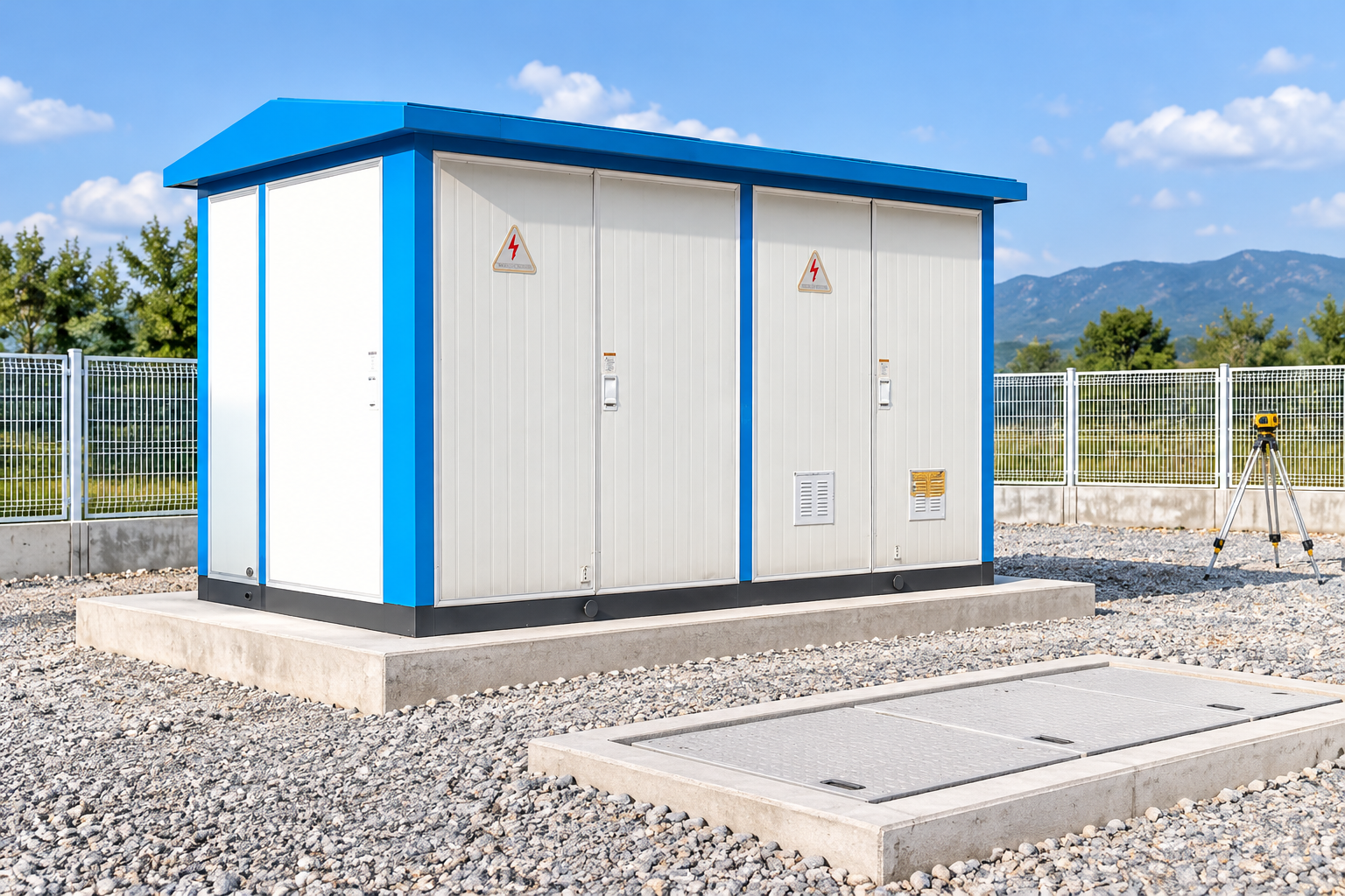
Accept civil dimensions and equipment interfaces before installation release. Reference-based illustration.
Receive and position the equipment
Inspect the delivery against the packing list and shipping records. Record visible damage, missing accessories and transport indicators where supplied. Preserve the manufacturer’s handling instructions and resolve discrepancies before moving the package into a position that restricts access.
The approved lifting method should address the actual equipment mass, lifting points, centre of gravity and crane configuration. A product photograph cannot provide those inputs. Do not infer lifting points from roof edges, door openings or other visible features.
Position the equipment against the accepted civil interfaces. Confirm orientation, cable entry alignment, access and required working space before final fixing. Keep enclosure ventilation openings and service routes clear. If the package arrives before installation conditions are ready, apply its specified storage and preservation measures.
Separate placement completion from electrical installation completion. A cabinet on its foundation may still need assembly checks, earthing connections, cable work, accessory installation and inspection. Mark those outstanding items clearly so the apparent progress does not create an incorrect readiness claim.
Install primary connections and auxiliary systems
Follow the approved cable schedule, termination instructions and equipment drawings. Confirm phase identification, cable suitability, routing, mechanical support and entry sealing. Installation inspection should be performed before areas are closed or concealed.
Auxiliary systems can include AC services, DC control power, protection, metering, communications and environmental controls. Their interfaces need separate checks. A healthy primary circuit does not prove that a trip path, alarm circuit or remote command works correctly.
Track changes against the design documents. If an equipment terminal or cable route differs from the approved drawing, resolve the discrepancy formally and update the records. An undocumented workaround can persist into commissioning and confuse the team responsible for future maintenance.
Keep construction and test status visible at the circuit level. Label circuits that are incomplete, under test or released, using the project’s agreed system. Control the boundaries where commissioning introduces test energy or where temporary supplies remain connected.
Start commissioning with a readiness review
Commissioning begins with an accepted installation, approved procedures and a clear test boundary. Collect factory records, site inspections, wiring checks, protection settings and instrument calibration information. Confirm that the test team has the correct drawing revisions.
A switchgear site acceptance checklist supports the switchgear portion of this stage. Maintain a distinct construction closeout record: a completed test does not automatically resolve drainage, access, sealing or civil defects.
Classify outstanding items by their effect on safety, operation and maintenance. Safety-critical or function-critical defects must be resolved before the affected system is released. Cosmetic or administrative items may require a controlled completion plan, but their acceptance belongs to the owner and responsible engineer.
Test integration as well as individual devices. Protection operation, interlocks, alarms, metering, communications and required remote functions should be checked through their intended paths. Preserve the test conditions and results so the owner can distinguish what was proven from what was merely inspected.
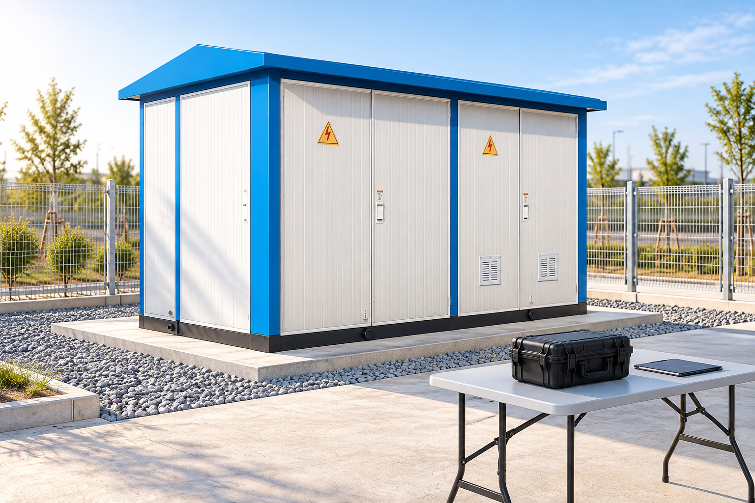
Keep installation acceptance separate from energization authorization. Reference-based illustration.
Authorize energization as a separate hold point
Energization changes the site’s hazards and responsibilities. It requires an approved switching programme, identified operating authority and confirmed readiness of the relevant systems. A project manager’s progress report is not a switching authorization.
Confirm the utility’s conditions, owner acceptance, operating documentation and personnel arrangements. Review access restrictions, emergency contacts and the handling of remaining construction work. Temporary grounds, test equipment and temporary connections must be controlled through the applicable approved process.
O US Bureau of Reclamation safety resources provide electrical safety context for its facilities. Their requirements must be interpreted within the applicable project framework, not copied as a universal energization procedure. The responsible operating authority sets the actual programme.
After initial energization, record the planned observations and acceptance criteria. Abnormal indications need investigation under the approved operating process. Do not invent a fixed observation period or advise repeated switching to see whether a fault disappears.
Handover should preserve the evidence
Deliver as-built drawings, final settings, equipment manuals, test reports, inspection records and the outstanding-item register. Include the responsibility for maintenance, warranty interfaces and future changes. The package should describe the installation that exists, not an earlier design revision.
Confirm that operators can locate isolation points, identify equipment and understand permitted access. Maintenance planning should reflect the supplied equipment and site conditions. Records of concealed work are particularly valuable when later repairs require excavation or access behind installed packages.
For schedule control, compare planned and actual releases. If cable installation was delayed by an entry mismatch, improve the drawing-interface review on the next project. If commissioning waited for missing auxiliary drawings, move that document hold point earlier. These lessons are more useful than applying an arbitrary shorter construction duration.
A successful sequence produces a safely accepted installation and a usable handover record. It does not merely produce equipment on a foundation by a target date. Keep each release tied to evidence and an accountable owner.
Further learning
American Transmission Co.’s educational video explains the role of commissioning engineers in substation construction. It provides utility context for the testing stage and the coordination involved. It does not specify the procedures or acceptance criteria for your project.
Further learning: What is commissioning? — American Transmission Co.. Educational background; this is not an operating authorization. Abrir o vídeo no YouTube.
Perguntas Frequentes
Is there one construction sequence for every substation?
The broad stages are similar, but their dependencies change with equipment type, site conditions, utility requirements and existing energized assets. Build the project schedule from approved interfaces and release criteria.
Can commissioning begin before all civil work is complete?
Some activities may proceed within an approved safe boundary, but incomplete civil work must not compromise the equipment or test conditions. The responsible parties should document what is released and what remains restricted.
Does factory testing remove the need for site acceptance?
Factory testing proves specified conditions before delivery. Transport, installation and system integration create additional interfaces that need the applicable site inspections and tests.
Who decides that the substation can be energized?
The designated operating authority, utility and owner follow the project’s approved authorization process. Installation progress or a generic checklist alone does not establish permission to energize.
A Shenheng Electric Power está empenhada em tornar-se líder global em soluções de equipamentos elétricos, ajudando os clientes a alcançar uma gestão de energia segura, eficiente e sustentável.
Se tiver alguma dúvida ou precisar de ajuda, não hesite em contactar a nossa equipa.
N.º 168, Estrada South Sixth de Punan, Zona de Desenvolvimento Económico de Yueqing, Cidade de Yueqing, Cidade de Wenzhou, Província de Zhejiang, China

 Shenheng Power Equipment Co., Ltd.