Desde 2001, a Shenheng Power tem sido um fabricante de confiança de equipamento de transmissão e distribuição de energia, fornecendo soluções elétricas fiáveis a nível global.
Apoiados por um sistema pós-venda completo, fornecemos consultoria técnica especializada, orientação de produtos e serviços flexíveis de OEM e ODM para os seus projetos.
Desde 2001, a Shenheng Power tem sido um fabricante de confiança de equipamento de transmissão e distribuição de energia, fornecendo soluções elétricas fiáveis a nível global.
Control power transformer sizing for switchgear starts with two separate checks: the continuous volt-ampere load and the temporary demand when operating coils pick up. A transformer that carries lamps, relays and holding coils comfortably may still allow the control voltage to fall during a closing operation. Build a device-by-device load schedule, define credible simultaneous operations, then verify the selected transformer against its manufacturer’s transient performance data and the connected devices’ minimum operating voltages. The breaker arrangement, auxiliary supply architecture and protective devices also matter. This guide explains how to prepare that calculation and the evidence needed before approving a purchase.
Define the control supply boundary first
An AC control power transformer supplies a defined group of auxiliary loads at the required voltage. It is not automatically the station service transformer, a voltage transformer used for measurement, or the battery system that keeps protection available during a supply failure. These functions can coexist in the same installation but have different duties and acceptance requirements.
Start with the single-line diagram and control schematic. Mark the transformer primary supply, secondary circuits, earthing arrangement and the equipment that depends on it. Establish whether the intended loads include contactors, closing coils, indication circuits, heaters, motor operators or electronic power supplies. Do not assume that every accessory in a switchgear lineup is connected to the same source.
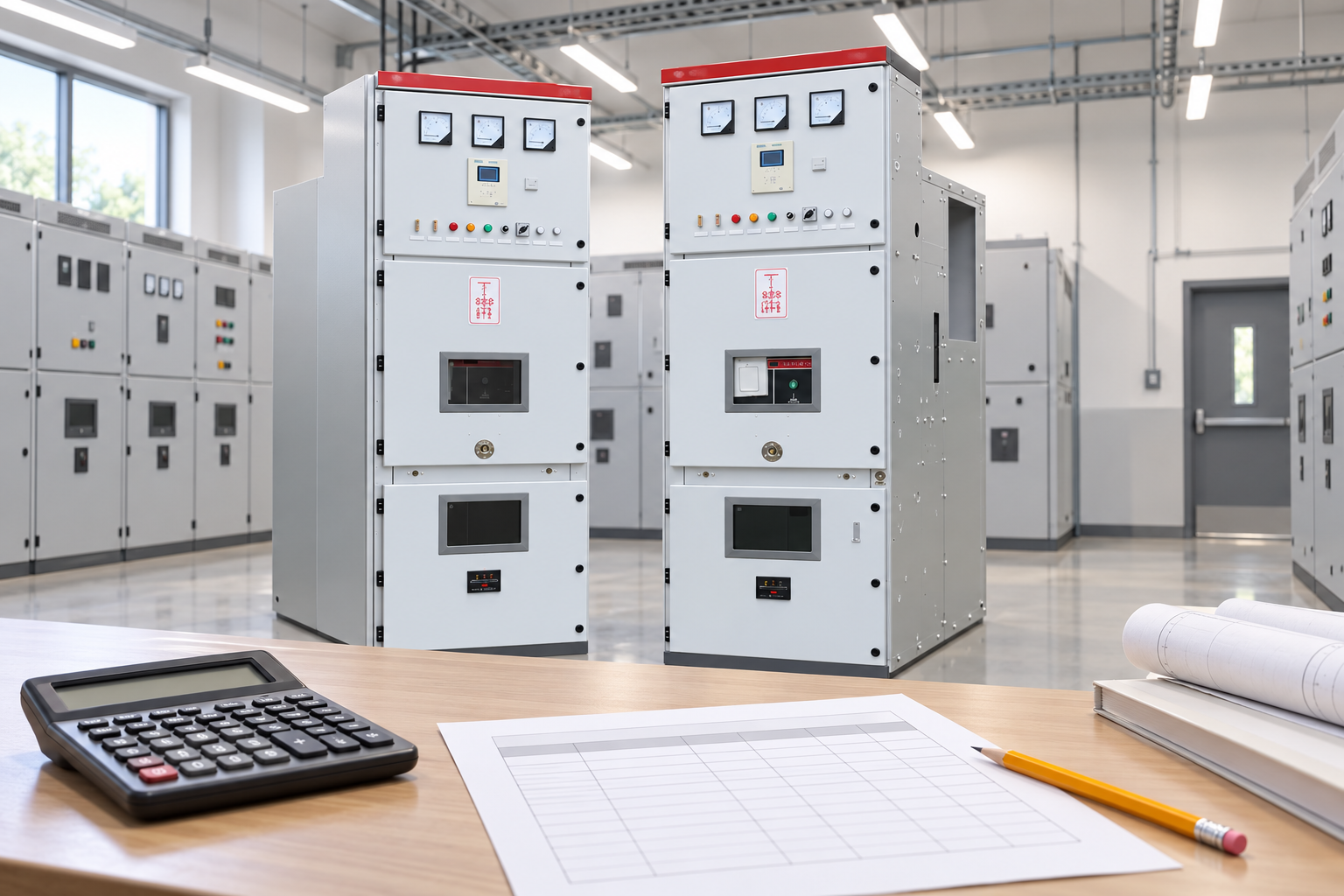
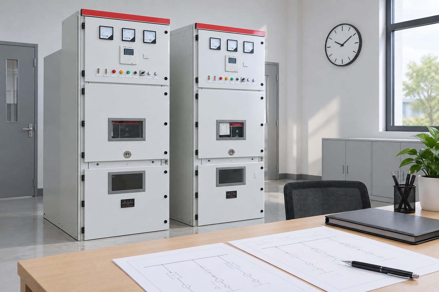
For equipment context, review the medium voltage switchgear guide and the actual KYN28 switchgear product. Product photographs establish the cabinet family; they cannot establish its internal auxiliary circuit or an available control transformer rating. Request the project-specific drawings before making that decision.
Build a load schedule with traceable inputs
For each device, record quantity, rated voltage, continuous or holding VA, pickup VA, operating duration and the permitted voltage range. Use the actual coil or accessory manufacturer’s data for the ordered version. Similar devices with different coil voltages can have different burdens, and a power value in watts is not necessarily the same as apparent power in VA.
O US Department of Energy electrical science handbook provides background on AC circuits and transformers. For this calculation, distinguish the current and apparent power that the supply must carry from the useful real power consumed by a device. Do not invent a power factor to convert a watt-only data sheet. Ask the supplier for the missing input instead.
Group loads by actual operation. A continuously energized relay belongs in the steady group. A contactor holding coil and its initial pickup demand represent different states of one device. A heater may be continuous under a specified cold-weather condition. A motor operator may run for longer than a brief closing pulse and needs its own duty assessment.
Entrada
Evidence to obtain
Why it affects selection
Holding or continuous VA
Ordered device data and quantity
Establishes sustained heating duty
Pickup VA and duration
Coil data at specified supply voltage
Establishes temporary voltage demand
Simultaneous operations
Approved control sequence and interlocks
Defines the credible combined event
Minimum device voltage
Manufacturer operating limits
Determines acceptable voltage at the load
Cable length and size
Project wiring schedule
Adds voltage drop outside the transformer
Ambient and enclosure conditions
Installation specification
Determines applicable rating or derating
The table is a design-input checklist, not a substitute for a manufacturer’s sizing chart. Missing pickup data is an unresolved design input, even when the continuous calculation is complete.
Record continuous and pickup burdens for the ordered accessories. Reference-based illustration.
Calculate continuous apparent power
For a single-phase secondary circuit, apparent power is S = V × I, where S is in volt-amperes, V is RMS volts and I is RMS amperes. When data are already provided in VA, add the applicable continuous loads directly. Preserve the voltage basis and operating state beside each input so another reviewer can reproduce the total.
As a hypothetical example, consider four devices with holding burdens of 10 VA each, two control relays at 6 VA each and indication circuits totaling 8 VA. The continuous total is 4 × 10 + 2 × 6 + 8 = 60 VA. At a nominal 120 V secondary, that represents 60 / 120 = 0.50 A. These values illustrate arithmetic only; they are not Shenheng product specifications or a recommended transformer rating.
If a documented 20 VA load will be added during an approved later stage, show it as a separate expansion input. The revised continuous total would be 80 VA. A clear expansion allowance is more useful than an unexplained percentage, particularly when the later equipment also creates a new pickup event.
Compare the continuous demand with the rating applicable at the specified frequency, ambient temperature and installation conditions. A transformer mounted inside a warm cabinet should not be assessed as though it has unrestricted outdoor cooling. Confirm the manufacturer’s installation conditions and any derating before choosing the next available rating.
Evaluate the worst credible pickup event
A coil can draw a larger temporary burden before its magnetic circuit closes. Adding only holding loads misses that event. However, adding every pickup burden in the entire lineup can exaggerate demand when the approved interlocks prevent those operations from occurring together. The correct event follows the real operating sequence.
For the same hypothetical schedule, suppose one 10 VA holding coil has a 180 VA pickup burden. If that coil changes from its holding state to pickup while the other loads remain active, the event total is 60 − 10 + 180 = 230 VA. If two such coils can credibly pick up together, the corresponding simple event total is 60 − 20 + 360 = 400 VA. Do not count the same coil’s holding and pickup burdens twice.
These sums organize the load schedule; they do not prove that a 230 VA or 400 VA nameplate transformer is required. Control transformers may be selected using manufacturer charts that relate continuous load, transient burden and permissible secondary voltage. Different designs can behave differently during short events. Obtain the correct chart or an explicit written selection from the supplier.
Include restoration after a supply interruption. Several relays or contactors may attempt to re-energize together even if normal commands are sequential. Also consider maintenance modes, local operation and automatic transfer where applicable. State which events are included and why excluded events are impossible under the approved logic.
Verify voltage at the connected device
The relevant acceptance point is the device terminals, not merely the transformer secondary. Primary voltage variation, transformer regulation, secondary protective devices, cable impedance and terminal connections can all affect the delivered voltage. Confirm the complete circuit under the relevant operating event.
Prepare the minimum primary supply assumption from the project’s approved electrical study or utility conditions. Then combine the supplier’s transient voltage information with calculated wiring drop. Compare the resulting voltage with the operating range of each coil or electronic supply. Use consistent RMS quantities and the correct timing basis; a steady-state cable calculation alone does not describe every transient.
Electronic loads may introduce additional considerations such as input current peaks or undervoltage shutdown. Request their actual input specifications instead of treating them as simple resistive burdens. If the selected supply feeds a DC power unit, evaluate the AC input burden and the downstream DC operating requirement separately.
Voltage problems should not be solved by changing a coil, transformer tap or protection setting informally. A change can affect other connected loads and the approved protection arrangement. Record the revision and repeat the affected checks before acceptance.
Check credible simultaneous commands and the device terminal voltage. Reference-based illustration.
Coordinate protection and availability
The primary and secondary protective devices must suit the transformer, wiring and connected loads while tolerating intended operation. A larger transformer can increase available fault current and may change the protection assessment. Selecting a larger rating without reviewing the surrounding circuit can therefore create a different problem.
Review isolation, earthing, overcurrent protection, conductor ratings and identification with the responsible electrical designer. The DOE electrical safety handbook provides electrical safety context for DOE facilities; it does not provide a universal control transformer sizing rule. Installation and testing require qualified personnel and the applicable local requirements.
Supply availability is a separate question from capacity. If the primary source disappears when a breaker opens, determine what control functions remain available. Protection tripping, closing and indication may have different continuity requirements. An adequately sized AC transformer cannot by itself provide battery autonomy during a supply outage.
Send the supplier the finalized device schedule, supply voltage and frequency, installation ambient, enclosure conditions, operating sequence and minimum permitted terminal voltage. Include spare capacity as named loads or a justified design allowance. Identify any devices whose data are provisional.
Request the selected model, continuous rating, transient selection method, applicable chart revision, predicted voltage under the worst event and any limitations. Ask whether the protective devices and wiring used in the assessment match the project. A quotation that lists only a VA rating is not enough to verify the calculation.
Before delivery, reconcile the calculation with the final accessory list. A changed closing coil, added heater or revised motor operator can invalidate an earlier selection. At acceptance, check identification and drawings, inspect the relevant circuits and perform the approved functional tests. Preserve the records with the switchgear factory acceptance checklist.
Further learning
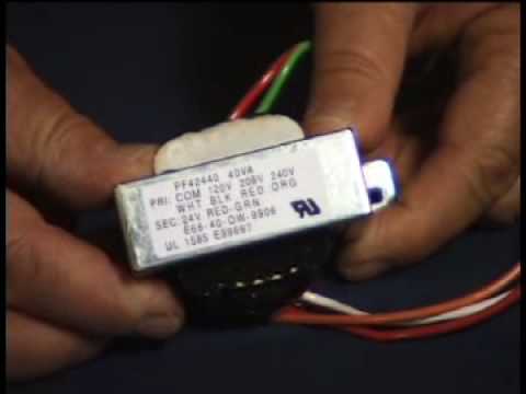
The following teaching video introduces control transformers and their construction. It provides useful component background; it does not replace the manufacturer’s transient sizing information or authorize live testing. The written calculation above remains the basis for reviewing the application.
Further learning: The Fundamentals of Control Transformers Part 1 — rawhidejim. Educational background; this is not an operating authorization. Abrir o vídeo no YouTube.
Perguntas Frequentes
Can I size a control transformer from continuous VA alone?
Continuous VA establishes sustained duty, but coil pickup and other temporary demands can determine whether the delivered voltage remains adequate. Check both the continuous load and the worst credible operating event.
Must all coil pickup burdens be added together?
Only combine operations that can occur together under the approved control logic, including restoration conditions. Document the sequence and interlocks rather than assuming either complete simultaneity or complete separation.
Is a larger transformer always the safest choice?
A larger rating may improve voltage performance, but it can affect protection, available fault current, space and thermal conditions. Verify the complete circuit instead of selecting capacity in isolation.
Does an AC control transformer replace the substation battery?
An AC transformer supplies power while its primary source is available. It does not inherently provide stored energy during an outage. Battery-backed control and protection require a separately assessed architecture.
A Shenheng Electric Power está empenhada em tornar-se líder global em soluções de equipamentos elétricos, ajudando os clientes a alcançar uma gestão de energia segura, eficiente e sustentável.
Se tiver alguma dúvida ou precisar de ajuda, não hesite em contactar a nossa equipa.
N.º 168, Estrada South Sixth de Punan, Zona de Desenvolvimento Económico de Yueqing, Cidade de Yueqing, Cidade de Wenzhou, Província de Zhejiang, China

 Shenheng Power Equipment Co., Ltd.