Desde 2001, a Shenheng Power tem sido um fabricante de confiança de equipamento de transmissão e distribuição de energia, fornecendo soluções elétricas fiáveis a nível global.
Apoiados por um sistema pós-venda completo, fornecemos consultoria técnica especializada, orientação de produtos e serviços flexíveis de OEM e ODM para os seus projetos.
Desde 2001, a Shenheng Power tem sido um fabricante de confiança de equipamento de transmissão e distribuição de energia, fornecendo soluções elétricas fiáveis a nível global.
K-Factor Transformers for Nonlinear Loads Explained
Release Time: 2026-10-13
A K factor transformer is designed and rated to carry specified nonlinear load currents without exceeding the applicable temperature limits under its stated operating conditions. Its K rating describes an ability to accommodate the additional heating associated with a harmonic current spectrum; it is not a harmonic filter, an efficiency percentage, or a power factor correction device. For a project buyer, the useful question is whether the documented transformer rating matches the measured or predicted load spectrum, continuous demand and installation conditions. A transformer photograph or the words “dry type” cannot establish that capability.
What the K rating tells a buyer
Nonlinear loads draw current that is not a smooth sine wave even when the supply voltage is reasonably sinusoidal. Drives, rectifiers, electronic power supplies and other conversion equipment can contribute harmonic components. The mix depends on the actual equipment and its operating mode. Treating every building containing electronics as the same load is therefore a poor specification method.
Harmonic current can increase winding eddy losses and other stray losses. A K rating addresses a particular thermal design problem rather than every power quality problem at once. A supplier must identify the applicable rating basis and operating limitations. A higher number does not automatically mean a better transformer for every installation, because required capacity, losses, ventilation, cost and the actual load all remain relevant.
This buying guide concerns specifying a new transformer for nonlinear loads. For evaluating the permissible loading of equipment already in service, read our separate transformer harmonic derating guide. The two decisions share current measurements but require different evidence: the first selects and verifies a supplied rating; the second assesses an existing thermal capability.
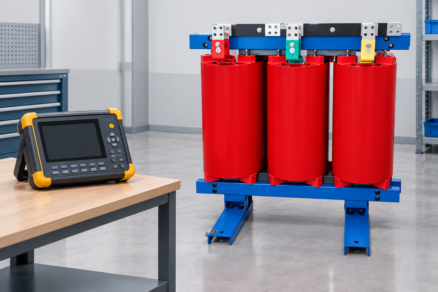
Current spectrum and reference basis support the assessment. Reference-based illustration.
Why total harmonic distortion is not enough
Total harmonic current distortion summarizes the combined harmonic current relative to its reference current. It does not retain the identity of each harmonic order. Two spectra with similar total distortion can distribute their current very differently among lower and higher orders. A weighted loss indicator can consequently differ even when the headline distortion percentage looks similar.
Measurements must also distinguish current distortion from voltage distortion. Recording only a voltage THD value at the main switchboard does not describe the currents passing through the transformer windings. The measurement location, load level, interval, instrument configuration and reference basis should accompany any number sent to a supplier.
Use representative operating states. A reading taken during a quiet shift may omit the combination of production equipment, cooling and computing loads expected at peak demand. Conversely, adding every equipment nameplate at full output may overstate simultaneous demand. A defensible specification describes normal operation, credible peaks, planned expansion and uncertainty explicitly.
A calculation example with a clear reference basis
A normalized harmonic loss weighting is FHL = Σ h²(Ih/Irms)², where h is harmonic order, Ih is the RMS current component of that order, and Irms is total RMS current including the fundamental. This expression illustrates why higher harmonic orders deserve attention. A rating-based K calculation instead uses the transformer rated RMS current as its current reference: K = Σ h²(Ih/Irated)². The two quantities coincide only when total RMS load current equals rated current. Confirm the definition and normalization used by the instrument and the proposed transformer rating before comparing results.
Consider a simplified hypothetical spectrum containing only a fundamental current of 100 A and a fifth harmonic of 20 A. Total RMS current is √(100² + 20²), approximately 101.98 A. The normalized weighting is (100² + 5² × 20²)/(100² + 20²), approximately 1.92. These numbers are an educational example, not measurements of a Shenheng product or a selection recommendation.
If the same 20 A component were instead at the eleventh harmonic, the weighting would be (100² + 11² × 20²)/(100² + 20²), approximately 5.62. Both simplified spectra have the same harmonic current magnitude relative to the fundamental, yet their weighted values differ substantially. Neither calculation by itself establishes the kVA required or authorizes loading an existing transformer.
Exclude nothing silently. Document the harmonic orders included, the treatment of unmeasured components, the current reference and whether measurements cover all phases. Zero sequence and neutral current questions require their own circuit assessment. Applying a value from one phase to every winding without checking the system can conceal an uneven duty.
Turn measurements into a procurement decision
The following table is a qualitative review checklist. It contains no universal rating thresholds; the project engineer and manufacturer must establish the applicable requirements using the actual load and equipment design.
Evidence requested
Why it changes selection
What a useful submission contains
Current spectrum
Different harmonic orders influence losses differently
Phase current components, measurement conditions and normalization
Continuous demand
Thermal duty depends on current magnitude as well as distortion
RMS demand, operating duration and credible simultaneous loads
Installation conditions
Cooling capability changes with the actual environment
Ambient range, altitude, enclosure and ventilation arrangements
Rating documentation
A marketing label does not define the supplied capability
Applicable rating basis, identified model and stated limitations
Neutral and connections
Circuit arrangement affects where currents flow
Approved winding connection, neutral arrangement and conductor assessment
Acceptance evidence
The ordered equipment must match the evaluated design
Drawings, nameplate schedule, specified verification and traceable records
Start with the load list and system diagram, then assign responsibility for measurements or predictions. For a new facility, ask equipment suppliers for input current characteristics at relevant load points rather than requesting only nominal power. For an existing facility, use a qualified power quality survey and preserve its underlying data.
O IEEE C57.110 standard record identifies guidance concerning transformer capability when supplying nonsinusoidal load currents. Its applicability and methods must be reviewed using the actual standard and transformer information; a public catalog page is not a substitute for its complete requirements. The published K-factor modeling study provides additional technical background on the relationship between current harmonics and transformer assessment. Neither reference certifies a particular supplied product.
K rating, kVA and harmonic mitigation are separate decisions
Choose capacity using the actual electrical demand and permissible operating conditions. KVA describes apparent power capability; K weighting describes characteristics of the harmonic duty under a specified basis. Replacing a demand study with a K number leaves the transformer size unresolved. Similarly, specifying additional kVA without evaluating harmonic losses may leave the thermal problem unresolved.
A transformer capable of carrying nonlinear currents does not necessarily remove those currents from the upstream network. If voltage distortion, resonance, sensitive equipment or utility limits create additional concerns, investigate mitigation as a separate engineering task. Filters, converter topology, system impedance and other measures have application limits and should be studied together.
Do not assume that two proposals with the same K label have equivalent losses, noise or installation requirements. Request the relevant loss information at defined operating conditions, the basis of any efficiency claim and the cooling arrangement. Evaluate those submissions against the project’s operating profile rather than an isolated headline specification.
How to read a supplier’s proposal
The proposal should identify a particular assembly and rating basis. Look for consistent voltage, frequency, phase arrangement, kVA, winding connection, insulation system, temperature rise information and installation conditions across the quotation, drawings and nameplate schedule. Record any exceptions before approval instead of allowing conflicting documents to survive into manufacturing.
Ask how the supplier evaluated the submitted spectrum and what assumptions were necessary. An answer that relies on an unspecified “typical nonlinear load” needs clarification. If the load changes materially after approval, return the new data for review; the original acceptance does not automatically cover a different duty.
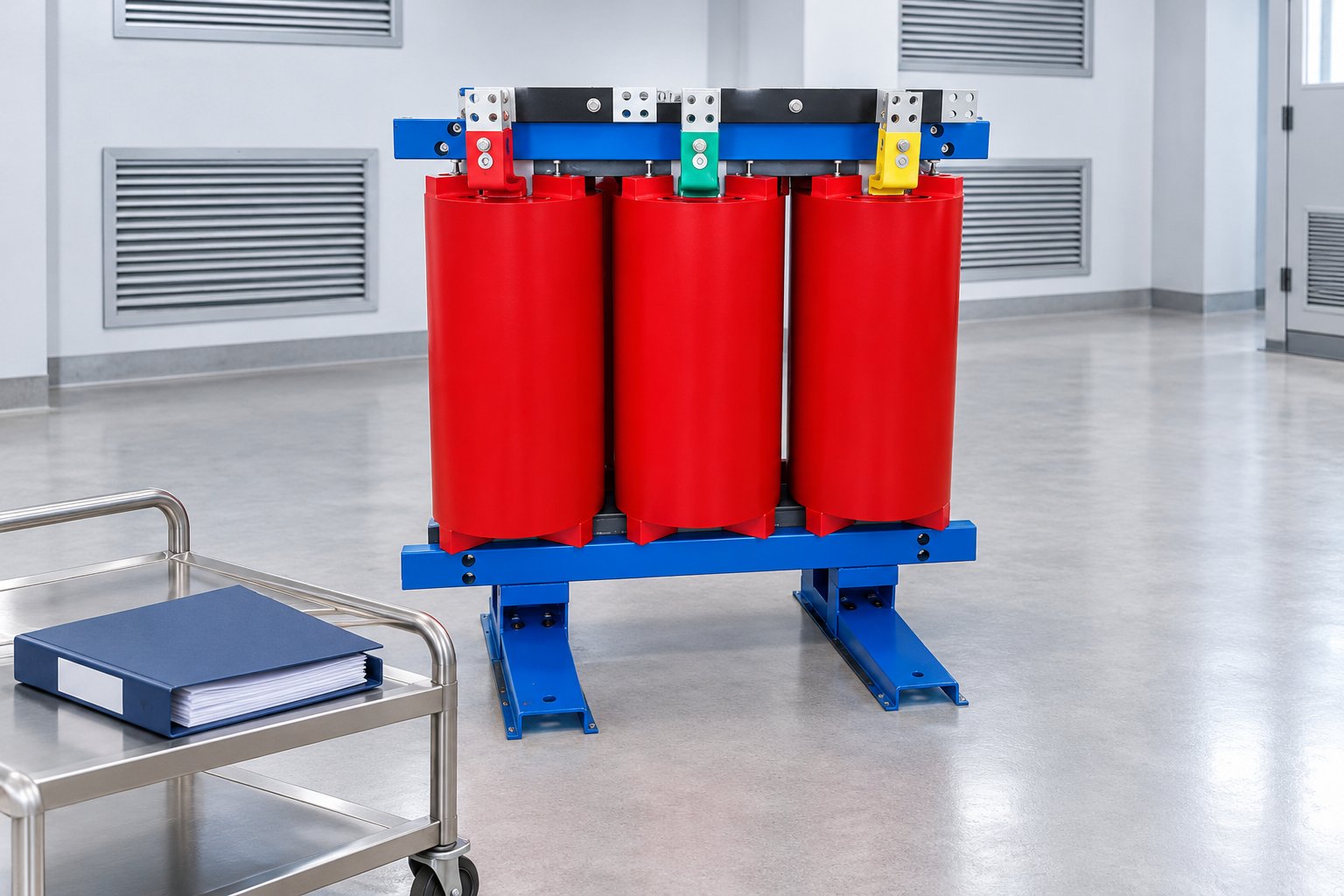
Our cast resin dry type transformer product page shows the equipment category used as the visual reference in this article. Its appearance is not evidence of a K rating. Obtain a written project specific proposal and supporting documentation before specifying any harmonic capability. For broader equipment choices, use the dry type transformer overview.
Preserve the installation assumptions underlying the proposal. Reference-based illustration.
Installation and acceptance checks
Installation must preserve the conditions on which the rating depends. Confirm the approved enclosure, clearances, ventilation path, room heat removal and ambient assumptions. A thermal capability assessed for unobstructed cooling may not apply inside a crowded enclosure with blocked air passages. Our dry type transformer ventilation guide addresses that separate installation question.
Electrical connections, protection and neutral arrangements also require the approved design. Do not infer conductor sizes or protection settings from a K rating. Installation and testing belong to qualified personnel following applicable local requirements and manufacturer instructions. Photographs in this guide illustrate equipment and review activities; they are not instructions for energized work.
At receiving inspection, compare equipment identity and documentation with the approved order. Before energization, complete the specified installation and commissioning checks. After operation begins, compare actual load conditions with the specification and review temperature trends using the approved monitoring method. Changes in ventilation or load mix should trigger reassessment rather than an assumption that the label covers every future condition.
Common purchasing mistakes
One common error is choosing a rating from the percentage of electronic loads alone. That percentage cannot replace the current spectrum and simultaneous demand. Another is mixing values normalized to the fundamental with values normalized to total RMS current without acknowledging the difference. Require the calculation basis whenever a proposal presents a derived number.
A third mistake is assuming the product reduces harmonics because it tolerates their heating effects. This can leave the upstream power quality objective unanswered. Finally, buyers sometimes treat a higher rating as permission to overlook environmental limitations. Cooling conditions, loading and the documented equipment design continue to constrain operation.
Keep a single decision record containing the submitted load data, calculation basis, selected capacity, required harmonic capability, installation assumptions, supplier exceptions and acceptance requirements. That record makes later changes assessable and helps maintenance teams understand why the equipment was selected.
Further learning
The following independent Power and Energy Channel explanation uses an electrical analysis environment to introduce K-rated transformers. It supplements the procurement discussion; it does not establish a product certification, replace a harmonic study or authorize equipment operation.
Further learning: What is K- rated transformer? — Power and Energy Channel. Educational background; this is not an operating authorization. Abrir o vídeo no YouTube.
Perguntas Frequentes
Is K factor the same as power factor?
No. Power factor relates real power to apparent power under a stated measurement basis. Transformer K weighting concerns the harmonic current spectrum and its thermal implications. One value cannot substitute for the other in a specification.
Does a K-rated transformer eliminate harmonic currents?
Not merely because it has that rating. Harmonic tolerance and harmonic mitigation are different functions. Evaluate filtering or other mitigation separately when the system requires it, using the actual network and load data.
Can a photograph prove that a transformer has the required rating?
No. Confirm the identified equipment, rating basis, operating limits and supporting documentation. A cast resin transformer photograph establishes visible equipment features, not its harmonic capability or compliance with an ordered rating.
Can I select a transformer using only a THD percentage?
No. Obtain the harmonic spectrum, current reference, simultaneous RMS demand and installation conditions. The supplier and project engineer need those inputs to evaluate the required capacity and harmonic capability together.
A Shenheng Electric Power está empenhada em tornar-se líder global em soluções de equipamentos elétricos, ajudando os clientes a alcançar uma gestão de energia segura, eficiente e sustentável.
Se tiver alguma dúvida ou precisar de ajuda, não hesite em contactar a nossa equipa.
N.º 168, Estrada South Sixth de Punan, Zona de Desenvolvimento Económico de Yueqing, Cidade de Yueqing, Cidade de Wenzhou, Província de Zhejiang, China

 Shenheng Power Equipment Co., Ltd.