Od 2001 roku Shenheng Power jest zaufanym producentem sprzętu do przesyłu i dystrybucji energii elektrycznej, dostarczającym niezawodne rozwiązania elektryczne na całym świecie.
Dzięki kompleksowemu systemowi obsługi posprzedażowej zapewniamy fachowe doradztwo techniczne, wskazówki dotyczące produktów oraz elastyczne usługi OEM i ODM dla Państwa projektów.
Od 2001 roku Shenheng Power jest zaufanym producentem sprzętu do przesyłu i dystrybucji energii elektrycznej, dostarczającym niezawodne rozwiązania elektryczne na całym świecie.
Transformer fire protection for oil filled equipment combines prevention, fault isolation, fire detection, exposure control, fluid containment and an appropriate emergency response. A suppression system is only one part of that design. Start with the transformer, fluid inventory, surrounding exposures and the facility’s risk criteria, then coordinate electrical, fire, civil and operating requirements. There is no universal nozzle arrangement or separation distance that fits every installation. This guide explains the design decisions and acceptance evidence needed for an oil transformer project, rather than prescribing a firefighting procedure.
Define the hazard and the design objective
Identify the transformer location, construction, insulating fluid, approximate inventory, operating duty and adjacent assets. The consequences of a fire beside a critical building differ from those at an isolated outdoor installation. Access for emergency responders, environmental receptors and the time needed to replace the equipment also affect the protection strategy.
State what the design is intended to achieve. Objectives may include limiting spread to adjacent plant, protecting people and escape routes, retaining contaminated liquids, supporting a controlled shutdown or reducing business interruption. Do not assume that installing a suppression system guarantees preservation of a transformer after an internal fault.
The Bureau of Reclamation’s transformer fire protection guidance discusses prevention, suppression and risk reduction in a power facility context. It is a useful technical reference, but its dated recommendations and facility assumptions must be assessed against current project requirements and the authority having jurisdiction.
Confirm the equipment and fluid before choosing protection
Obtain approved general arrangement drawings, fluid information, accessory schedules, protection diagrams and the manufacturer’s installation requirements. A purchase description such as oil immersed transformer does not establish the actual tank volume, fluid fire characteristics or the presence of a particular protective device.
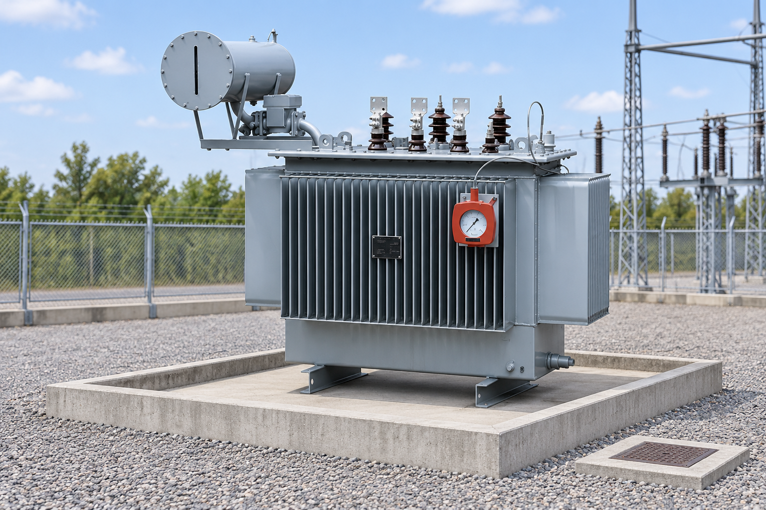
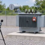
For the conservator oil transformer product family, request project specific equipment information before developing fire interfaces. Reference illustrations show the equipment category; they are not drawings of an approved fire protection installation.
Fluid substitution is a separate engineering decision. A higher fire point fluid does not automatically remove the need for containment, electrical protection or exposure assessment. Compatibility, thermal performance, seals, maintenance and the applicable approval route require review. Use the mineral oil and natural ester comparison for that distinct procurement question.
Keep prevention and electrical isolation in the design
Condition monitoring, maintenance and protection can help identify problems and limit electrical energy supplied to a fault. They do not eliminate every possible fire scenario. A protection study should define the intended fault clearing behavior, the breakers that must operate and the consequences of a failed trip path.
Fire related control logic needs a documented interface with that protection scheme. Identify who owns each signal, how it is powered, how a loss of supply is reported and which actions require operator intervention. Avoid treating every alarm as an automatic trip or every trip as a confirmed fire. The design should distinguish equipment condition, electrical fault and fire detection functions.
The transformer differential protection guide addresses electrical protection coordination. Do not copy a generic relay setting into a fire design. The responsible engineers should agree the cause and effect schedule and verify it against the actual equipment and facility operating philosophy.
Assess fluid containment and firefighting drainage together. Reference-based illustration.
Assess separation and barriers against real exposures
Map adjacent transformers, buildings, cable routes, occupied areas and critical services. Consider how released oil, flame and heat could affect them. A barrier may interrupt a particular exposure path, but its required geometry, construction and interfaces depend on the assessed hazard and applicable standards.
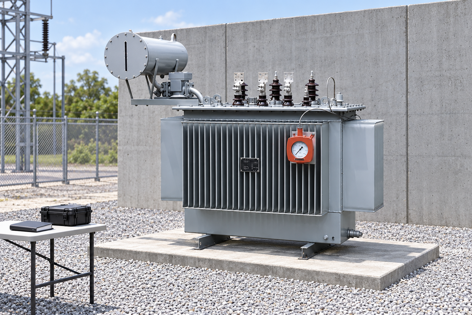
Check openings, penetrations and the continuity of the proposed barrier. A concrete wall in a photograph is not evidence of a fire resistance rating. Its structural support and any seismic requirements also need design review. Position it so that cooling, electrical distances, inspection and major equipment removal remain feasible.
Separation and barriers should be evaluated alongside active systems rather than selected independently. A constrained site may require a different combination of measures from an open yard. Record the reasoning and approvals instead of assuming that a neighboring installation provides a suitable template.
Coordinate the protection layers
This table is a design interface checklist informed by the Reclamation fire protection reference and its transformer maintenance guidance. It contains no universal suppression rates, response times or construction dimensions; those must come from the approved project design.
Protection layer
Question to resolve
Evidence needed
Common interface failure
Condition and maintenance
How are developing equipment problems detected and escalated?
Inspection and condition assessment procedures
Fire design assumes maintenance removes all risk
Electrical isolation
Which sources and breakers must be addressed?
Protection study and trip matrix
One energized source is omitted
Fire detection
Which fire scenarios should be detected and how?
Detector selection and coverage assessment
Detection chosen without considering outdoor conditions
Separation or barrier
Which neighboring exposure is being protected?
Site hazard assessment and approved construction
Wall conflicts with access or cooling
Suppression
What hazard, supply and performance basis applies?
Engineered system design and calculations
Nozzles selected from a generic picture
Containment and drainage
Where do oil and firefighting liquids go?
Civil volume and drainage assessment
Added water overwhelms the containment concept
Control interfaces
What happens on alarm, operation or loss of supply?
Cause and effect schedule and test plan
Unreviewed shutdown or missing supervision
Emergency response
Who isolates, calls for assistance and controls access?
Facility response plan and training record
Equipment instructions mistaken for responder procedure
Select detection for the environment and fire scenario
Detector technology and placement must suit the expected fire behavior and environmental conditions. Outdoor sunlight, weather, obstructed views and normal equipment heat can influence the assessment. The specialist designer should explain the basis for coverage and the handling of faults, maintenance and unwanted alarms.
Coordinate detection with the equipment geometry. Conservators, radiators, barriers and other structures can affect visibility or access. Review changes to the transformer or yard against the detection design rather than assuming the original coverage remains adequate.
Keep inspection and test access practical. A detector that cannot be checked safely creates a maintenance problem from the beginning. Define the required test method, records and impairment procedure with the owner so that temporary loss of protection is controlled and communicated.
Evaluate suppression as an engineered system
Water spray or another suppression approach may be appropriate when supported by the hazard assessment and governing requirements. The design must address supply reliability, hydraulic performance, coverage, component suitability, environmental conditions and maintenance. There is no safe shortcut from transformer rating to a complete system arrangement.
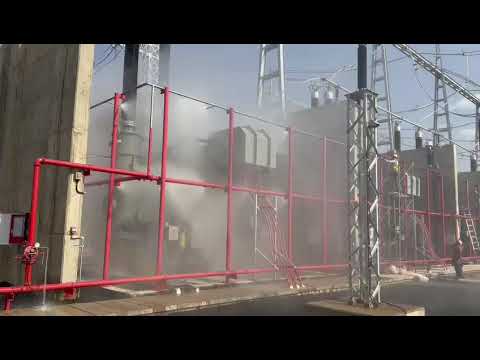
A deluge system uses open outlets supplied through a controlled valve arrangement. Its engineering must establish how the system is initiated, supervised, tested and restored. Do not infer the required discharge from an online demonstration. A video can illustrate operation without supplying the calculations or approval basis for a different site.
Resolve interactions with transformer auxiliaries through the approved control design. The Reclamation reference discusses cooling equipment and fire response interfaces, but equipment specific actions require confirmation. An unreviewed control change can affect transformer cooling, fire behavior or other plant functions. The final sequence must be agreed by the electrical, fire and operations teams.
Design containment for the combined event
A transformer fire scenario can involve both released insulating liquid and firefighting water. Rainfall, drainage state and other site contributions may also matter. The civil design should identify the selected event assumptions and how contaminated liquids are retained, transferred or treated.
A containment wall alone does not prove that liquid will remain on site. Check penetrations, drain paths, valve arrangements and possible overflow routes. Confirm that normal drainage and emergency retention do not depend on an action that nobody is assigned or able to perform during the event.
Użyj transformer oil containment guide for the separate volume and drainage coordination task. Keep its assumptions consistent with the suppression design. If the selected firefighting arrangement changes, revisit the containment assessment before approving the change.
Retain fire protection interface and acceptance evidence. Reference-based illustration.
Test the complete cause and effect chain
Plan acceptance before construction is complete. Define which tests demonstrate component operation, control logic, supervision, communication and the intended interfaces. A detector test alone does not establish that the correct alarm reaches the control room or that the isolation sequence is correct.
Coordinate test modes with the operator. Any inhibited trips, isolated valves or temporary bypasses need controlled authorization, clear indication and restoration checks. A functional test must not create an unexpected equipment shutdown or uncontrolled discharge. The commissioning method should be specific to the installation and led by qualified personnel.
Retain test results, outstanding defects and their disposition. Where full integrated testing cannot be completed, describe the limitation and the remaining acceptance action. Do not replace an unperformed test with a general statement that individual components were supplied with certificates.
Prepare the operating and emergency handover
Provide accessible drawings, valve and detector schedules, control logic, inspection requirements, impairment procedures and response contacts. Mark the responsibilities of the facility operator, equipment manufacturer, fire protection contractor and emergency service. A clear ownership boundary is particularly important where several contractors supply different protection layers.
Training should address recognizing alarms, maintaining access, reporting impaired protection and following the facility’s emergency plan. This article does not instruct untrained personnel to approach burning electrical equipment or apply water. Response depends on electrical isolation, site conditions and trained emergency management.
Review the design after changes to fluid, equipment arrangement, barriers, cooling, drainage or adjacent assets. Maintain a record of the change and its effect on the original hazard assessment. Fire protection is an ongoing facility function, not a drawing that can be filed away after energization.
Further learning: a utility deluge system demonstration
Kenya Electricity Transmission Company Limited demonstrates a transformer firefighting deluge system at a converter station. The video illustrates an installed utility system. Its arrangement should not be copied as a design for the illustrated product or another project.
Further learning: Transformer Firefighting Deluge System — Kenya Electricity Transmission Company Limited. Educational background; this is not an operating authorization. Otwórz wideo na YouTube.
Często zadawane pytania
Does every oil transformer need the same fire suppression system?
No. The appropriate combination of prevention, isolation, separation, containment, detection and suppression depends on the equipment, exposures, applicable requirements and risk assessment. A qualified project design must establish the protection strategy.
Can a fire barrier replace all other protection measures?
A barrier addresses particular exposure paths. It does not automatically provide electrical fault isolation, fluid containment, detection or an emergency response plan. Evaluate it as one coordinated protection layer rather than a complete solution.
Is the oil volume enough to size a containment area?
Not by itself when the selected event includes firefighting water, rainfall or other contributions. The civil and fire designers must agree the relevant inputs, retention strategy and drainage behavior for the approved scenario.
What should a transformer fire protection enquiry include?
Provide equipment and fluid data, site and exposure drawings, protection interfaces, water supply information, containment constraints and the required approval and acceptance process. State the design objectives and ask suppliers to identify all assumptions and exclusions.
Shenheng Electric Power zobowiązuje się do zostania światowym liderem w dziedzinie rozwiązań w zakresie sprzętu energetycznego, pomagając klientom w bezpiecznym, wydajnym i zrównoważonym zarządzaniu energią.

 Shenheng Power Equipment Co., Ltd.