Od 2001 roku Shenheng Power jest zaufanym producentem sprzętu do przesyłu i dystrybucji energii elektrycznej, dostarczającym niezawodne rozwiązania elektryczne na całym świecie.
Dzięki kompleksowemu systemowi obsługi posprzedażowej zapewniamy fachowe doradztwo techniczne, wskazówki dotyczące produktów oraz elastyczne usługi OEM i ODM dla Państwa projektów.
Od 2001 roku Shenheng Power jest zaufanym producentem sprzętu do przesyłu i dystrybucji energii elektrycznej, dostarczającym niezawodne rozwiązania elektryczne na całym świecie.
Transformer Inrush Current: Causes, Effects and Protection
Release Time: 2026-09-22
Transformer inrush current is a temporary magnetizing current that can occur when a transformer is energized. It results from the relationship between applied voltage, switching instant, residual core flux and magnetic saturation. It can be much greater than normal no-load current, but it is not automatically a winding fault or an overload. Protection must tolerate the expected energization behavior while remaining sensitive to genuine faults. The correct assessment uses the actual transformer, source network, switching arrangement and relay scheme rather than a universal current multiplier.
What changes at energization?
In steady operation, the applied voltage establishes an alternating magnetic flux. At the moment of energization, the initial flux condition depends on the previous state of the core and the voltage waveform at switching. That combination can produce a flux excursion into a region where additional magnetizing current is required.
The event is influenced by residual magnetism, source impedance, transformer design and the timing of the switching device. Three-phase energization also depends on pole behavior and connection. Consequently, successive energizations of the same transformer may not produce identical recordings. A single successful energization does not define every possible condition.
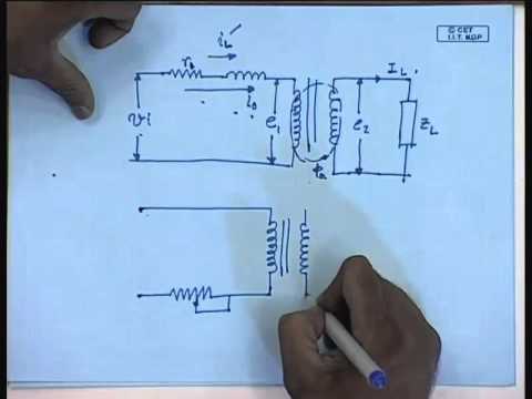
A useful teaching reference is IIT Bombay’s NPTEL material on magnetizing inrush. It provides background for understanding the phenomenon; the field assessment must still use manufacturer and protection-engineering evidence for the particular installation.
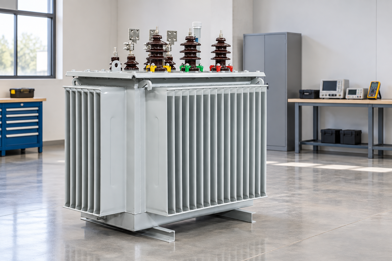
Use the actual transformer and source data to assess the energization duty. Reference-based illustration.
Separate inrush, loading and fault conditions
Observation
Possible interpretation
Evidence needed before deciding
Current begins with energization and decays
Magnetizing inrush may be present
Current waveform, switching time and voltage record
Current remains high after energization
Load, abnormal operating condition or fault
Load status, phase currents and equipment inspection
Differential element operates
Internal fault or protection behavior needs review
Differential and restraint quantities, event report and CT data
Nearby energized transformer current changes
Sympathetic inrush may be relevant
Network arrangement and simultaneous recordings
Voltage dips during energization
Source response to transient current
Source impedance and voltage-sensitive load behavior
Current is abnormal without a switching event
Do not assume ordinary energization inrush
Complete operating history and protection investigation
The table is a diagnostic planning aid, not permission to bypass protection. A relay trip should be investigated through the authorized procedure. Do not repeatedly reclose a transformer while assuming that every trip is harmless inrush.
Why a fixed multiple of rated current is inadequate
A headline value such as a fixed number of times full-load current can be useful as a rough illustration, but it does not specify peak versus RMS current, averaging interval, duration or network condition. Those distinctions affect breaker, fuse and relay coordination differently. Using an unspecified multiplier in a tender can therefore create an apparent agreement without a usable engineering requirement.
Ask for the expected envelope or study assumptions for the offered transformer. Identify whether the information describes peak current, an RMS window or an approximate time-current characteristic. State the source condition and residual-flux assumption where applicable. Compare equivalent quantities when reviewing competing offers.
For reference, full-load current is a separate steady-state calculation. On the three-phase side, I = S / (sqrt(3) × V), with consistent units. A 1,000 kVA, 11 kV example gives approximately 52.5 A. This number is an illustrative rated-current calculation, not an estimate of inrush amplitude or the rating of a particular website product. See the full-load current calculation guide for the underlying distinction.
Relay discrimination and CT behavior
Transformer differential protection compares currents after accounting for ratio, phase relationship and other scheme requirements. Energization creates a situation in which magnetizing current may appear as differential current. The protection scheme therefore needs a validated method of distinguishing an expected transient from an internal fault.
Some schemes use harmonic information or other waveform characteristics. The exact method, thresholds and blocking logic belong to the relay application, not a generic article. A universal second-harmonic setting is inappropriate because transformer design, network conditions and relay algorithms differ. Obtain the protection engineer’s settings and validation record.
Review CT ratio, class, burden, wiring and saturation behavior as part of the same assessment. An event report that contains only a trip indication is insufficient to explain what the relay measured. Collect the recorded quantities and the configuration active at the time of the event before changing settings.
Overcurrent and fuse coordination
The feeder protection must coordinate with expected energization current and with downstream protection while meeting fault-clearing requirements. Evaluate the current-time characteristic, minimum operating behavior and the margins required by the project. The correct task is to establish an acceptable coordination region, not simply raise a setting until the nuisance trip disappears.
For a fuse-protected transformer feeder, use the fuse manufacturer’s coordination evidence for the actual switch-fuse combination and transformer duty. Consider interruption capability, striker operation, overload behavior and the implications of single-phase operation where relevant. A fuse rating chosen from rated transformer current alone is incomplete.
The RMU fuse-selection guide addresses that feeder interface. It complements the inrush explanation because it examines the complete protection selection rather than treating the energization transient as the only design condition.
Voltage disturbance and neighboring loads
An energization current can cause a temporary voltage change depending on source impedance. Sensitive controls, drives or process equipment may be affected even when the transformer itself energizes successfully. Describe those loads in the study and specify the voltage performance the facility requires.
Review whether several transformers are energized together or sequentially. A new transformer can also influence already energized units through the shared network. Capture recordings at appropriate locations if sympathetic inrush is suspected. Looking only at the new feeder may omit an important part of the system response.
The designer should compare realistic source cases, including an alternative supply or a weak-network condition if the site uses one. A result calculated for the strongest source may not represent commissioning under temporary supply. State those assumptions in the energization plan so operators know which arrangement has been reviewed.
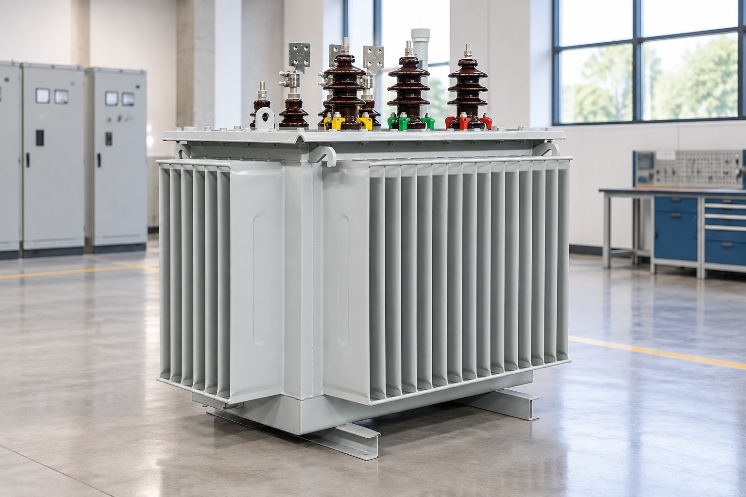
Preserve event recordings before changing protection settings. Reference-based illustration.
Practical mitigation options and their limits
Mitigation can include an approved switching strategy, controlled switching where applicable, suitable energization sequence or another engineered arrangement. Selection depends on the voltage level, equipment design, operating pattern and project economics. No single measure is automatically appropriate for every distribution transformer.
Changing the energization sequence may reduce disturbance in one network but affect restoration time or protection coordination. Controlled switching requires compatible devices, sensing and a validated control strategy. Any proposed mitigation should be reviewed for failure behavior as well as normal operation: what happens if timing information, control power or a controller becomes unavailable?
Do not improvise a series resistor, add an unapproved device or alter transformer connections in the field. The owner should require a complete proposal that addresses insulation, switching duty, thermal behavior, protection and operational instructions. Commissioning should confirm the claimed improvement with a defined measurement plan.
Investigating a trip during commissioning
Preserve the relay event report before it is overwritten. Record the exact energization time, breaker position, connected load, supply arrangement and whether the transformer had recently been disconnected. Note the active settings and any recent wiring or software changes. These details are essential for distinguishing a transient from an installation problem.
Check the approved commissioning records, including transformer identification, ratio and connection information, CT polarity and relay injection results. Investigate alarms and physical symptoms through qualified personnel. Abnormal sound, smoke, leakage or protection evidence requires escalation; it should not be dismissed because the event occurred during energization.
OSHA’s electrical work-practice requirements are a useful safety reference for isolation and verification before inspection. Follow the local rules and approved switching program. The purpose of the investigation is to establish a safe explanation, not to defeat a protective function.
Data to request with the transformer
For a relevant inquiry, the oil-immersed transformer product category example identifies the equipment being discussed. Request the actual offered unit’s ratings, connection, impedance, test reports and available energization information. Do not infer its transient performance from a product photograph or a general catalog description.
Provide source fault levels, source impedance information, feeder arrangement, switching device details, protection equipment and sensitive-load requirements. Ask the supplier and protection engineer to identify missing inputs before procurement. A late discovery that a required waveform or compatibility statement is unavailable can delay commissioning.
Keep the energization study with the asset documentation. Also connect it to the Przewodnik dotyczący pomiaru mocy transformatorów, since rated capacity and transient behavior answer different questions. A larger transformer is not automatically the easiest unit to energize on a weak source.
Further learning
Further learning: Mod-01 Lec-09 Lecture-09-Harmonics and Switching Transients in Single Phase Transformers — nptelhrd. This educational video supports the topic; it is not a product demonstration or an operating authorization. Otwórz wideo na YouTube.
Często zadawane pytania
Is transformer inrush current the same as starting load current?
No. Magnetizing inrush concerns energizing the core. Connected motor or other load starting can occur at the same time, but it must be identified separately in the network and protection assessment.
Can a transformer trip even when it has no connected load?
Yes. Magnetizing current can be significant during no-load energization. However, a trip still needs investigation; no load does not prove that the equipment is free of internal faults or wiring problems.
Should the relay setting simply be increased?
No. A setting change must preserve required fault sensitivity and coordination. Use recorded event data, the transformer characteristics and the relay application to identify an approved solution.
What measurement is most useful?
Time-synchronized current and voltage waveforms with relay event information are valuable. Also record the source configuration, switching time, transformer history and the settings active during the event.
Shenheng Electric Power zobowiązuje się do zostania światowym liderem w dziedzinie rozwiązań w zakresie sprzętu energetycznego, pomagając klientom w bezpiecznym, wydajnym i zrównoważonym zarządzaniu energią.

 Shenheng Power Equipment Co., Ltd.