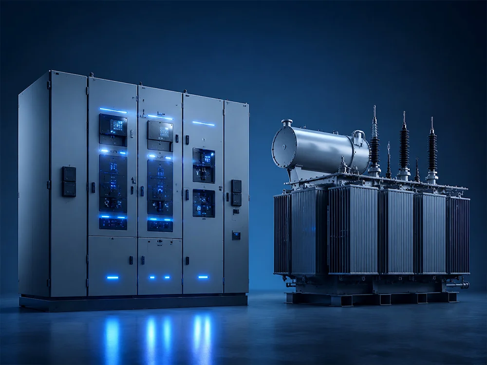
A 変電所の接地システム 埋設導体、接地棒や電極、機器ボンディング、構造物、フェンス、中性線、ケーブルシールド、および表面処理の相互接続されたグリッドであり、危険な接触電圧およびステップ電圧を制限しながら、地絡電流および雷電流のための制御された経路を提供するものです。優れた接地は、1つの低い抵抗値を追い求めることによって達成されるものではありません。設計においては、最大グリッド電流、地絡継続時間、土壌抵抗率と層構造、導体の熱容量、グリッド形状、移行電位、人体への影響、腐食、および保護の遮断時間を考慮する必要があります。施工の前に、資格を持った者による接地スタディとプロジェクトの準拠規格が必須となります。.
地絡時には、電流が接地系統に流れ込み、変電所のグリッドをリモートアース(遠方大地)の電位以上に上昇させます。このグリッド電位上昇は避けられないものであり、安全上の課題は、人間がまたぐことのできる電位差を設計基準内に収めること、および導体がその事象に耐えられるようにすることです。露出した導電部をボンディングすることによりそれらを共通の電位に近づけ、一方、埋設された形状と表面材料によって電位勾配を形成します。.
IEEE Std 80 AC変電所の接地に関する安全性への指針を提供する。プロジェクトごとに最新版と現地の要件を確認しなければならない。IEC規格に基づくプロジェクトでは、その他の方法を使用してもよい。グリッドの間隔を単にコピーすることや、「各コーナーに1本のロッドを配置する」といった規則は設計ではない。.
| 要素 | 主要な目的 | 設計上の懸念 |
|---|---|---|
| 埋設格子状導体 | 電流および制御面の勾配を分散する | 形状、深さ、熱負荷、腐食 |
| 接地棒/接地極 | より深い土壌に届き、現在の分散を補う | 土壌層、間隔、施工時の損傷 |
| 設備債 | タンク、フレーム、キャビネット、構造物、ニュートラルを接続する | 短く信頼性の高いパスとアクセスしやすい関節 |
| フェンスとゲートの保証金 | アクセス可能な境界電位を制御する | 移行電圧と可動関節 |
| 表層 | 足元抵抗を上げる | 材料の電気抵抗率、厚さ、水分、メンテナンス |
| つながり | グリッドの連続性を維持する | 故障率、腐食、施工品質、検査 |
適切な電極間隔と敷地内の複数箇所で土壌抵抗率を測定する。1回の測定では、層状、岩石質、埋め立てられた、湿潤な、あるいは季節によって変化する地盤を説明することはできない。この調査では、現場データを土壌モデルに変換し、不確かさを記録する。導電性の埋め土を投入した後や異常な水分状態で測定されたデータは、最終的な敷地を代表していない可能性がある。.
グリッド電流の計算は、単に開閉装置の短絡定格を用いるものではありません。グリッドに流入する地絡電流の割合、架空地線、中性点、ケーブルシース、隣接する接地系統を通る帰路、および故障点を考慮します。保護遮断時間は、導体の加熱と許容される暴露時間の両方に影響します。承認された短絡および保護スタディを使用してください。.
フェンス、ゲート、道路、制御建物、機器基礎、ケーブルトレンチ、レール、配管、通信ルート、引き込み線、近隣の建物、および一般立ち入りエリアを記載してください。主要機器付近の値が許容範囲内であっても、敷地境界におけるタッチ・ステップ電圧の曝露が設計を左右する場合があります。.
接触電圧 接地された物体と足元の表面の間で人がまたぐことのできる電位差。. ステップ電圧 2つの足の間の表面電位差です。メッシュ電圧とは、格子状のメッシュ内で計算される接触曝露電圧のことです。. 移流電位 導体、シールド、配管、レール、または中性線が変電所の電位を別の場所に運ぶこと、あるいは遠隔地の電位を構内に持ち込むことによって発生する。.
電位の移転には、局所的なグリッド計算だけでなく、境界(インターフェース)の検討が必要です。金属製の水道管、通信ケーブルのシールド、低圧中性線、フェンスの延長、遠隔パネルなどが予期せぬ経路を作り出す可能性があります。絶縁、等電位化、サージ保護、あるいは電位勾配制御策を、実際のシステムに合わせて設計しなければなりません。.
Transformer tanks, radiators where required, marshalling kiosks, switchgear frames, operating handles, cable boxes, surge arresters, steel structures, control-building steel, metallic cable trays, fences, gates, and auxiliary systems need defined bonds. A single daisy chain can make downstream equipment dependent on one joint; critical items may require two independent connections to different grid points.
Neutral grounding connections carry system current under specific faults and must not be treated as ordinary equipment bonds. Their route, CT position, parallel paths, and connection to the grid affect protection. Coordinate transformer neutral, grounding resistor or reactor, station service, and LV neutral arrangements with the protection study.
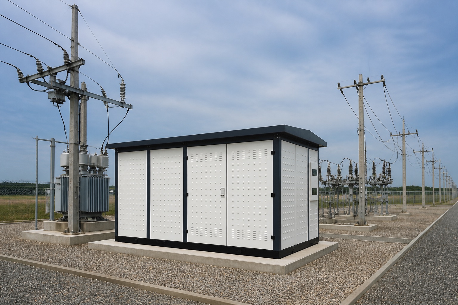
The buried grid becomes difficult to inspect once civil works advance. Establish hold points for conductor depth and routing, connection method, rod installation, foundation interfaces, riser locations, material compatibility, and photographic records. Protect conductors from concrete-work and excavation damage. Keep connections clean and make them with the qualified process.
Update as-built coordinates when the route changes around foundations or services. A drawing that shows the design but not field deviations weakens future testing and excavation safety. Record every accessible test point and equipment bond label.
Commissioning may include visual inspection, continuity testing of the grid and equipment bonds, verification of conductor routing before burial, soil or system measurements, and specialized integrity testing. A simple clamp measurement at one bond does not prove the safety of the entire grid. Test methods, limits, current injection, remote probes, and interpretation depend on the system and standard.
EPRI has researched substation ground-grid condition assessment, reflecting the difficulty of evaluating buried systems. During service, inspect corrosion, broken flexible gate bonds, construction damage, added equipment without bonds, loose accessible joints, fence changes, and civil modifications. Revisit the study when fault levels, clearing times, footprint, soil, or connected metallic systems materially change.
Test results depend on current paths, probe placement, connected neutrals and shields, soil condition, interference, and instrument method. Compare readings with the study model and earlier tests made under similar conditions. An unexpected value should trigger a setup and grid-configuration review before excavation. Conversely, one satisfactory overall resistance measurement cannot close a defect involving a broken equipment bond or unsafe perimeter gradient.
A permanent ground grid does not eliminate the need for isolation, absence-of-voltage verification, and temporary protective grounding during work. It also does not guarantee zero voltage during faults. OSHA’s 電気安全に関するリソース provide regulatory context in the United States. Switching, equipotential work zones, induced voltage, and temporary grounds require site-specific procedures.
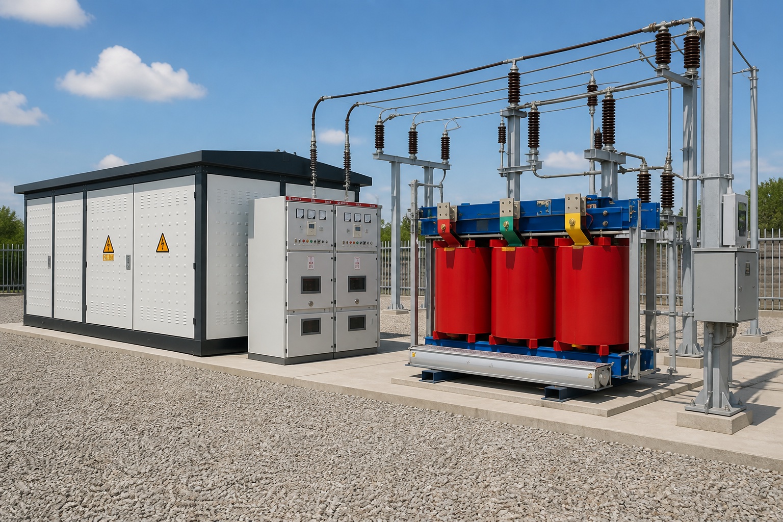
For a prefabricated or compact substation, the vendor should identify enclosure bonding points, transformer tank bonds, MV/LV switchgear bonds, neutral connection, cable-shield connections, internal conductor size, and interface to the external grid. The project engineer remains responsible for integrating the package into the site grounding study.
Review Shenheng’s 11/33 kV compact outdoor substation. Complementary planning pages include the compact-substation foundation guide, switching-substation commissioning, 、および substation maintenance checklist.
This independent educational video illustrates grounding, step potential, and touch potential. It is conceptual and does not replace a grounding study.
受容境界 The finished grounding system should be accepted against the engineered study, approved drawings, material and connection requirements, construction inspections, as-built record, and specified tests. A generic target copied from another substation cannot account for this site’s soil, fault-current split, clearing time, accessible areas, or transferred potentials. Unresolved departures require engineering disposition before energization.
単一の抵抗値だけでは安全性を証明できません。実際の地絡および土壌の条件に対して、設計は接触電圧、ステップ電圧、熱、およびプロジェクトの要件を満たさなければなりません。.
A suitable high-resistivity surface layer can increase foot-contact resistance and reduce body current, but material properties, thickness, moisture, contamination, and maintenance matter.
Requirements depend on the item, standard, owner practice, and reliability objective. Major equipment often uses multiple deliberate paths; drawings must define them.
故障電流、遮断時間、敷地の形状、機器、フェンス、土壌条件、または接続された金属系に重大な変更が生じた場合は、それを更新してください。.
No. It verifies selected conductive paths but does not alone prove soil performance, current distribution, or acceptable touch and step voltages.


 申恒電力設備有限公司.