Dal 2001, Shenheng Power è un produttore affidabile di apparecchiature per la trasmissione e la distribuzione di energia, che fornisce soluzioni elettriche affidabili a livello globale.
Supportati da un completo sistema post-vendita, offriamo consulenza tecnica esperta, guida sui prodotti e servizi flessibili OEM e ODM per i vostri progetti.
Dal 2001, Shenheng Power è un produttore affidabile di apparecchiature per la trasmissione e la distribuzione di energia, che fornisce soluzioni elettriche affidabili a livello globale.
Voltage Transformer Selection for Medium Voltage Panels
Release Time: 2026-10-10
Voltage transformer selection for switchgear should begin with the system connection and the measurement or protection duty, then establish the ratio, winding arrangement, accuracy, burden, insulation and installation requirements. A voltage rating alone does not define a suitable VT. The selected assembly must provide the signals required by the connected devices while fitting the panel’s approved electrical and mechanical design. For a medium voltage buyer, a useful specification therefore connects the VT data sheet to the single-line diagram, secondary circuits and acceptance tests. This guide focuses on that selection process for inductive VTs, with project-specific values left to the approved design.
Establish which voltage the circuit must measure
Start by naming the required quantities. A metering circuit, directional protection function, synchronizing arrangement and residual-voltage protection function can require different signals. State whether each connected device needs phase-to-phase, phase-to-earth or another defined voltage. Do not infer the connection from an incomplete ratio written in an inquiry.
The primary system arrangement and grounding method affect this choice. The designer should identify the nominal system voltage, highest equipment voltage, frequency and expected abnormal operating conditions. A phase-to-earth VT application needs a different review from a phase-to-phase application even when both are installed on the same nominal network. Include the relevant voltage factor and duration requirements in the approved specification.
The IEC 61869-3 catalogue identifies the standard for inductive voltage transformers used with measuring instruments and protective devices. Confirm the project edition and the relationship with the general instrument-transformer requirements. The catalogue is an authoritative scope reference, not a substitute for the purchased standard or equipment test evidence.
Write the ratio with its connection context
Specify primary and secondary rated voltages in a way that clearly identifies the winding connections. A number containing a square-root-of-three relationship should not be stripped of that context when transferred to a purchase order or relay setting sheet. Record the terminal designation and the intended measured quantity alongside each winding ratio.
For example, a balanced system relationship between line-to-line and phase-to-neutral voltage does not prove that every relay input is connected phase-to-neutral. Verify the actual drawing. The relay’s scaling configuration must reproduce the intended primary quantity from the signal it receives. A plausible display value at one operating point can conceal a connection or scaling error.
Check the available secondary voltage against the connected devices’ rated inputs and approved configuration. Existing panel meters, relays and synchronizing equipment may impose compatibility requirements. A replacement VT selected with a different secondary voltage can require more than changing a display multiplier. Review insulation, input ratings and every downstream function before approving a substitution.
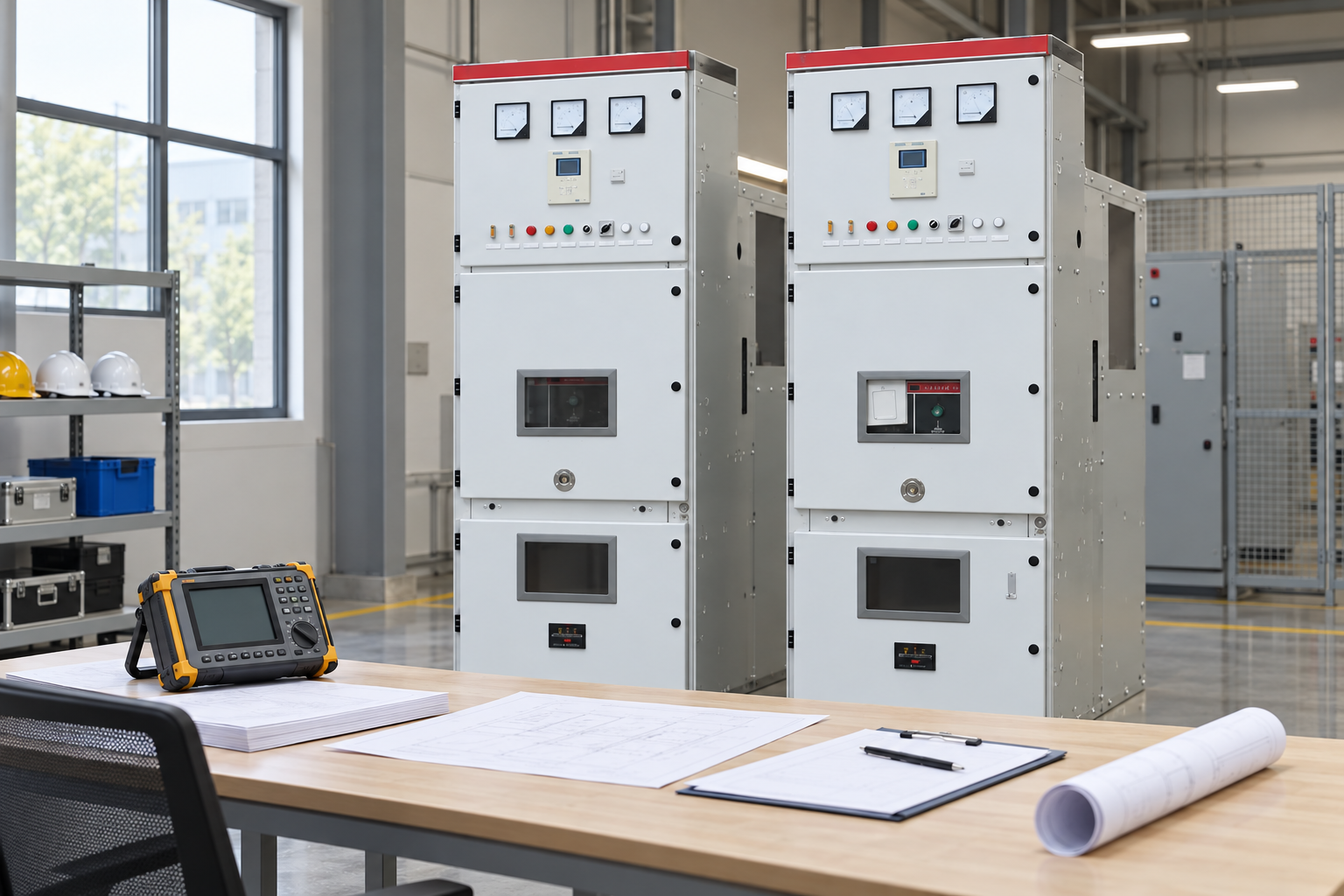
Review ratio, winding duty and connected burden together. Reference-based illustration.
Allocate secondary windings by duty
List the devices connected to each secondary winding. Separate metering, protection and residual-voltage duties where the design requires separate windings. Identify accuracy requirements for the actual use of each winding rather than applying one class indiscriminately to the whole assembly. A revenue metering requirement and a protective function need their own justification.
Where a residual-voltage connection is required, specify its winding arrangement and the intended protection input. Explain how the residual signal is formed and supervised. The winding labels, connections and relay settings must agree. A drawing that shows a residual winding but omits the associated burden or wiring details leaves the application unfinished.
Consider future additions conservatively. Reserve capacity should be a documented design allowance rather than an excuse to purchase an arbitrarily large burden rating. Future devices still need a circuit review, and a winding’s accuracy conditions must remain satisfied after they are added. Keep spare terminals clearly identified so later work does not unintentionally share incompatible circuits.
Calculate burden for the installed circuit
The connected burden includes the relevant devices and the secondary circuit effects defined by the application. Assemble a schedule using actual device data, operating conditions and the proposed wiring. For electronic inputs, use the manufacturer’s stated burden rather than assuming that every device has the same demand. For long runs, evaluate voltage drop and its effect on the required accuracy.
Evaluate the complete winding circuit. A VT can satisfy its own specified accuracy while the voltage delivered to a remote device is affected by lead impedance, poor connections or circuit protection. The acceptance question is therefore two-part: does the offered VT meet its specified duty, and does the installed circuit deliver the required signal at the device?
Document the maximum and relevant minimum operating burden conditions where required by the selected accuracy specification. An unusually lightly loaded winding may need consideration as well as a heavily loaded one. The applicable standard and manufacturer’s data define the conditions; do not invent a universal accuracy guarantee for any burden below the nameplate maximum.
Check grounding and abnormal voltage duty together
The VT application must be compatible with the network grounding method and the conditions that can persist during an earth fault. This affects insulation and voltage duty, and can affect the treatment of residual-voltage circuits. Ask the protection designer for the actual requirement and duration rather than selecting a voltage factor from a generic table without its assumptions.
Secondary grounding should follow a controlled design that defines the reference point and avoids unintended parallel grounding paths. The designer must also specify the relevant circuit protection and supervision. CT and VT secondary practices are different: a VT secondary short circuit can be damaging, while an open energized CT secondary can be hazardous. Do not transfer a CT testing habit to a VT circuit by analogy.
Some inductive VT applications require a review of ferroresonance and damping arrangements. The risk depends on the circuit, switching conditions and equipment characteristics. Treat it as an application review with the manufacturer and network designer, not as a reason to add an unspecified component. Any damping equipment must have an approved connection, duty and verification method.
Review panel fit and safe maintenance access
Electrical suitability does not prove mechanical compatibility. Confirm mounting dimensions, clearances, terminal positions and the panel arrangement. If the assembly is withdrawable, review its interlocks, primary and secondary connection sequence, earthing provisions and handling procedure. An equivalent nominal ratio does not make two assemblies interchangeable inside the same switchgear.
Identify the facilities used for testing and isolation. The commissioning team should be able to establish the prescribed test boundary without improvised connections. Ask how the VT circuits are isolated from relays, how the secondary reference is maintained during approved tests and how restoration is verified. These are acceptance questions, not instructions for unqualified live work.
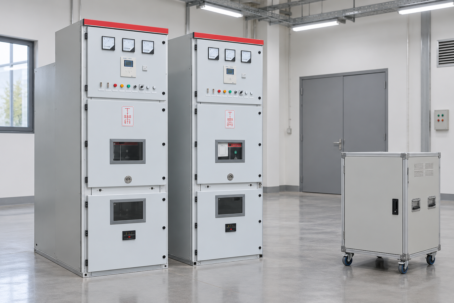
For a Shenheng medium voltage switchgear package, request the offered instrument-transformer details and panel drawings before approving the arrangement. The reference images illustrate the cabinet family. They do not show a particular internal VT or prove that all options are included in every cabinet.
Use a purchase review table with specific deliverables
Selection decision
Information to specify
Evidence to obtain
Measured quantity
Phase-to-phase, phase-to-earth and residual requirements
Single-line and secondary diagrams
Ratio
Each winding voltage and connection context
Data sheet and terminal identification
Winding allocation
Devices and functions on each winding
Circuit schedule and relay input requirements
Accuracy
Duty-specific class and applicable conditions
Relevant test evidence for the offered winding
Burden
Device demand, wiring and future allowance
Installed burden and voltage-drop review
Voltage duty
Grounding method and abnormal-voltage duration
Approved system and manufacturer application review
Installazione
Mounting, clearances, withdrawal and isolation
General arrangement and interlock documentation
Acceptance
Ratio, polarity, wiring and functional checks
Test plan and traceable results
The table intentionally contains no universal rating recommendations. Every value should follow the actual network and device requirements. This makes bids comparable without suggesting that a standard cabinet photograph establishes the instrument duty.
Check the installed secondary circuit against the approved drawings. Reference-based illustration.
Verify the signal from primary reference to relay input
Acceptance should establish the correct assembly identity, winding ratio, polarity and terminal connections. Match test reports and markings to the installed unit. Use the approved methods and limits for insulation and ratio checks; connected electronic devices may need isolation before certain tests. The test plan must distinguish equipment tests from installed-circuit checks.
Check phase sequence, grounding and secondary circuit protection against the drawings. Verify the scaling and measured quantities at the receiving device. Where a directional or synchronizing function depends on a voltage reference, include a functional test appropriate to that duty. Proving a meter display alone does not establish the operation of every protection function sharing the circuit.
A substitution review should compare every winding, voltage duty, accuracy condition, burden requirement and mechanical interface. A proposed unit can be similar in size and primary rating while differing in a protection winding or abnormal-voltage capability. Ask the supplier to identify differences explicitly and obtain designer approval before installation.
Record the final configuration in the handover documents, including devices connected to each winding and their scaling settings. Later additions can change burden or grounding paths. Changes to a network’s grounding arrangement can alter the VT application without changing the cabinet. Assess those changes before assuming the original acceptance result remains applicable.
Keep the article’s selection boundary distinct from the wider medium voltage switchgear overview. Cabinet classification, breaker rating and instrument-transformer duty are linked project decisions, but they answer different questions. A complete procurement package should document all three without using one as proof of the others.
Further learning: voltage transformer selection
The educational video below discusses the selection and sizing process. Use it as further explanation of the design questions; the project standard, drawings and manufacturer evidence govern the actual assembly.
Further learning: Voltage Transformer Selection and Sizing | IEC | Part 1 | Substation Design — Electrical Thunderbolt. Educational background; this is not an operating authorization. Apri il video su YouTube.
Domande frequenti
Is the nominal voltage enough to select a VT?
No. The system connection, measured quantity, secondary duty, burden, accuracy, abnormal voltage requirements and panel compatibility also need review. Nominal voltage is only one input.
Can one secondary winding serve metering and protection?
It may be possible if the design and winding specification support all connected duties and burden conditions. The designer must verify accuracy, circuit protection and functional requirements; shared wiring should not be assumed suitable by default.
Why does the system grounding method matter?
Grounding affects voltages during earth faults and the duty of phase-to-earth equipment. The selected VT and any residual-voltage arrangement must be reviewed for the actual operating conditions and required duration.
What should be checked after replacing a VT?
Confirm equipment identity, ratios, polarity, terminal mapping, grounding, circuit protection, connected burden and receiving-device scaling. Repeat the affected functional checks and update the controlled drawings and test records.
Shenheng Electric Power si impegna a diventare un leader globale nelle soluzioni di apparecchiature elettriche, aiutando i clienti a ottenere una gestione dell'energia sicura, efficiente e sostenibile.

 Shenheng Power Equipment Co., Ltd.