Desde 2001, Shenheng Power ha sido un fabricante de confianza de equipos de transmisión y distribución de energía, ofreciendo soluciones eléctricas confiables a nivel mundial.
Respaldados por un sistema postventa completo, ofrecemos consulta técnica experta, orientación sobre productos y servicios flexibles de OEM y ODM para sus proyectos.
Desde 2001, Shenheng Power ha sido un fabricante de confianza de equipos de transmisión y distribución de energía, ofreciendo soluciones eléctricas confiables a nivel mundial.
Monitoreo de temperatura en transformadores de tipo seco: sensores, alarmas y tendencias
Release Time: 2026-08-30
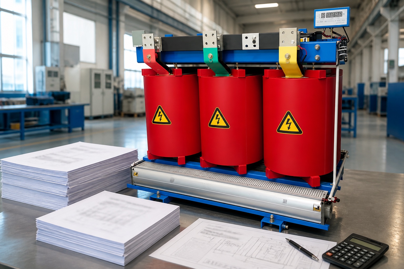
Dry type transformer temperature monitoring tracks the thermal condition of windings, core area, enclosure air, and cooling system so operators can detect overload, blocked ventilation, fan failure, connection heating, or sensor problems before they develop into an outage. Cast-resin units commonly use embedded resistance-temperature sensors connected to a controller for display, alarms, fan control, and trip contacts. Infrared inspections and load data add context but do not replace embedded winding measurements. Alarm values must come from the transformer manufacturer, insulation system, sensor location, site conditions, and approved protection philosophy—not from a universal internet setting.
Why temperature is a condition indicator
Transformer losses become heat. Core loss is present whenever the transformer is energized, while winding loss rises strongly with current. The thermal result also depends on ambient temperature, ventilation, enclosure design, harmonics, load cycle, altitude, dust, and the operation of fans. A high reading can therefore be a symptom rather than a diagnosis.
Dry-type transformers do not have circulating oil to distribute heat, so airflow and local winding temperature deserve careful attention. A monitoring system supports early warning, but the ordered transformer’s rated temperature rise and insulation class define its design boundary. IEEE C57.12.01 covers general requirements for dry-type distribution and power transformers, while IEC 60076-11 may govern projects using IEC requirements. Always use the edition named in the contract.
Embedded sensors and room airflow should be reviewed together because winding temperature depends on load and cooling conditions.
What should be monitored
Monitoring point
What it can reveal
Important limitation
Embedded winding sensors
Phase temperature trend and thermal imbalance
Reads the installed sensor location, not every possible hot spot
Ambient or enclosure air
Room and ventilation influence
Sensor placement must avoid misleading drafts or hot exhaust
Fan status
Cooling availability and control sequence
A run command does not prove airflow
Infrared inspection
Surface hot spots and connection imbalance
Emissivity, line of sight, load, and enclosure barriers affect results
Load current and harmonics
Electrical cause of heating
Must be time-aligned with temperature data
Embedded sensor systems
Platinum resistance sensors such as Pt100 devices are frequently embedded near windings in cast-resin transformers. Their resistance changes predictably with temperature, and a controller converts that signal into a displayed value. The controller may provide independent phase channels, fan start/stop relays, high-temperature alarm, trip output, sensor-fault indication, communication, and event history.
Sensor type, lead configuration, shielding, isolation, and controller input must match. A two-wire measurement includes lead resistance; three- and four-wire arrangements can compensate more effectively. Do not megger through connected electronic sensors or controllers. Disconnect and protect monitoring circuits exactly as specified by the manufacturer before insulation testing.
Alarm, fan, and trip philosophy
A practical scheme separates operating actions. Fan control can start forced cooling before an alarm. An alarm warns operators to investigate load, ambient, airflow, and phase balance. A higher trip stage may initiate protective action when continued operation creates unacceptable risk. Time delay and hysteresis prevent relay chatter near a threshold.
Settings are not interchangeable across transformers. Insulation thermal class does not automatically equal an acceptable continuous sensor reading, because rated temperature rise, ambient basis, hot-spot allowance, sensor placement, loading guide, and enclosure design all matter. Record manufacturer-approved values in the commissioning sheet and protect changes through access control.
Lista de verificación de puesta en marcha
Confirm transformer nameplate, insulation system, cooling designation, enclosure, rated rise, and approved temperature schedule.
Map each sensor to the correct phase and location. Compare controller channel labels with drawings.
Verify sensor continuity and plausible room-temperature readings before energization.
Test fan rotation, airflow direction, filters, louvers, interlocks, and local/remote control.
Inject or simulate sensor values using the approved method to prove fan, alarm, trip, and supervisory contacts.
Confirm communication scaling, timestamps, engineering units, alarm text, and loss-of-signal behavior.
Record baseline phase temperatures under a known stable load and ambient condition.
Verify that protection actions agree with the cause-and-effect matrix and do not create an unsafe automatic restart.
Electrical work must follow the site energy-control and arc-flash program. OSHA’s electrical safety resources provide regulatory context; the site procedure and equipment instructions govern the task.
Temperature performance depends on the complete installation: transformer design, load, enclosure, clearances, and room ventilation.
How to interpret trends
All phases rise together
Check total load, ambient temperature, fan availability, blocked filters, recirculating hot air, room exhaust, and recent operating changes. A proportional rise with load can be normal; a new departure from the established baseline deserves review.
One phase is consistently hotter
Compare phase current, harmonic content, sensor behavior, terminal connections, and airflow. A loose or resistive connection may create localized surface heating without the same pattern as an embedded winding sensor. Qualified infrared inspection can help localize the issue.
Temperature changes abruptly
An instantaneous step with no load or airflow change often suggests sensor, lead, controller, scaling, or communication trouble. A genuine winding thermal change normally follows a thermal time response rather than an impossible jump.
Fans run but temperature continues rising
Verify actual airflow direction and volume, not only the relay output. Look for failed individual fans, clogged passages, open doors that disrupt the designed path, hot-air recirculation, or load beyond the approved forced-cooled rating.
Infrared thermography: useful but limited
Thermography can compare phases, locate hot terminals, and show blocked cooling patterns while equipment is carrying representative load. However, painted metal, shiny connections, viewing windows, distance, focus, reflections, and emissivity can distort apparent temperature. Enclosures also hide internal parts. A thermogram should record load, ambient condition, camera settings, image location, and visual photograph.
Thermal imaging near energized equipment must stay within the electrical-safety program and equipment access rules. Do not open a door simply to obtain a better image without an energized-work assessment.
Data and alarm management
Trend each phase temperature with ambient temperature, load current, fan status, and alarms on the same clock. Retain enough history to compare similar load and seasonal conditions. Use rate-of-rise and phase difference as investigation prompts, but avoid automated conclusions unsupported by the transformer design.
Alarm notifications should identify the asset, channel, actual value, stage, timestamp, and fan state. Operators need a response instruction: verify load and cooling, inspect remotely where possible, escalate to the responsible engineer, and apply the approved shutdown plan if required. Acknowledging an alarm must not disable protection.
Building a useful thermal baseline
Capture baseline data after commissioning at several known load points rather than relying on one snapshot. Record ambient and room inlet temperature, phase currents, fan state, enclosure condition, and time allowed to approach thermal stability. Compare similar operating conditions: a summer peak should not be judged against a lightly loaded winter reading without context. Keep phase relationships visible because a stable difference can be more informative than one absolute value.
After changes to room ventilation, filters, enclosure panels, load profile, harmonics, sensor wiring, controller firmware, or fans, establish a new documented baseline while retaining the previous record. The change history helps distinguish a real transformer trend from a measurement or installation change.
Procurement questions for monitoring
Which sensors are embedded, where are they located, and how many wires are brought out?
Which controller channels, relays, communications, and supply voltages are provided?
What are the manufacturer-recommended fan, alarm, and trip settings?
What happens on sensor open circuit, short circuit, controller power loss, or communication loss?
Are fans rated for the environment and accessible for safe replacement?
What room airflow, clearances, ambient range, and altitude assumptions apply?
Which factory functional tests and site commissioning records will be supplied?
Límite de aceptación: Monitoring helps operators recognize abnormal thermal behavior, but it does not create extra transformer capacity. Loading decisions must remain within the approved rating, ambient, enclosure, ventilation, altitude, harmonic, and cooling assumptions. When alarms recur, correct the cause rather than repeatedly raising thresholds. Any setting change should be approved, version-controlled, function-tested, and reflected in the operating response plan.
Preserve alarm and trip event records for engineering review.
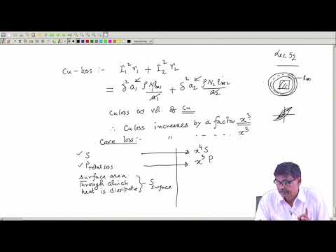
This independent electrical-engineering lecture explains transformer cooling and heat removal. Confirm all site settings independently against the ordered transformer.
Dry type transformer temperature monitoring FAQ
Where are dry-transformer sensors installed?
They are commonly embedded near windings, with exact locations selected by the manufacturer. Additional sensors may monitor core area, ambient air, or enclosure exhaust.
Can one universal trip temperature be used?
No. Settings depend on the transformer design, rated rise, insulation system, sensor location, ambient basis, cooling arrangement, and approved protection philosophy.
Does a fan-run signal prove cooling?
No. It proves a command or auxiliary contact state. Airflow direction, individual fan condition, filters, and passages must also be checked.
Can infrared imaging replace embedded sensors?
No. Infrared imaging measures visible surface radiation and is valuable for connections and comparisons, while embedded sensors provide continuous internal-location trends.
What data should be trended together?
Trend phase temperatures, ambient or enclosure temperature, phase currents, fan status, alarms, and relevant harmonic or ventilation information on synchronized timestamps.
Shenheng Electric Power se compromete a convertirse en un líder mundial en soluciones de equipos eléctricos, ayudando a los clientes a lograr una gestión de energía segura, eficiente y sostenible.

 Shenheng Power Equipment Co., Ltd.