Seit 2001 ist Shenheng Power ein vertrauenswürdiger Hersteller von Energieübertragungs- und -verteilungsausrüstung und liefert weltweit zuverlässige elektrotechnische Lösungen.
Unterstützt durch ein umfassendes Kundendienstsystem bieten wir kompetente technische Beratung, Produkthinweise sowie flexible OEM- und ODM-Dienstleistungen für Ihre Projekte.
Seit 2001 ist Shenheng Power ein vertrauenswürdiger Hersteller von Energieübertragungs- und -verteilungsausrüstung und liefert weltweit zuverlässige elektrotechnische Lösungen.
Transformer oil leaks can result from deteriorated seals, damaged joints, fittings, tank defects or problems in the preservation and pressure arrangement. The visible wet area is not always the actual leak source because oil can travel across surfaces before dripping. Assessment should establish the location, rate, oil level, associated alarms and environmental consequences before choosing a response. Do not tighten joints, apply sealant or repeatedly add oil as an unapproved field remedy. Qualified personnel and the transformer owner must determine isolation, repair and return-to-service requirements for the specific asset.
Begin with a safe condition assessment
Record the transformer identification, operating condition, oil-level indication, alarms and visible leak location from an approved safe position. Consider hot surfaces, pressure, energized parts and spill hazards before approaching equipment. An accessible drip point does not make a nearby electrical installation safe to touch.
If protection operates, oil level is abnormal or the condition is worsening, escalate through the owner’s procedure. Do not use a general online guide to authorize continued operation. The response depends on the equipment, observed condition, network role and applicable safety and environmental rules.
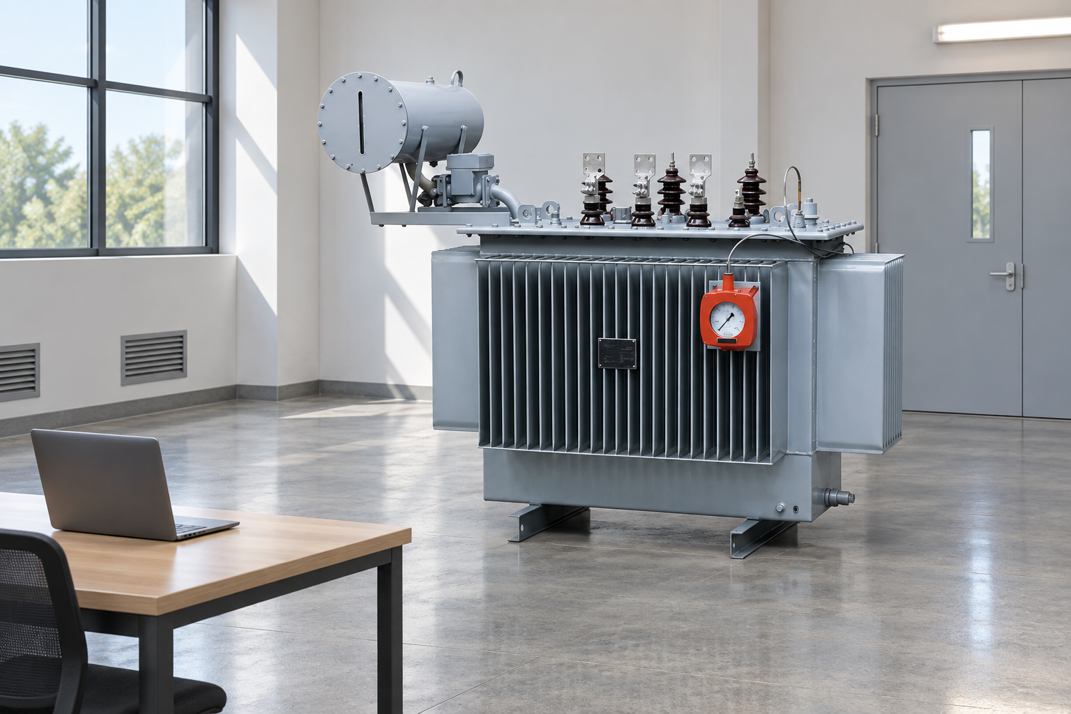
Plan approved repair, fluid handling and acceptance before the outage. Reference-based illustration.
Common locations and investigation questions
Observed area
Possible source to investigate
Useful evidence
Important limitation
Cover or flange
Seal deterioration, joint condition or pressure effects
Cleaned inspection under an approved procedure
Oil can travel from another location
Bushing mounting
Gasket or surrounding connection condition
Qualified inspection and accessory identification
Electrical and mechanical risks require control
Valve or plug
Fitting, seal or previous maintenance
Work history and exact component details
Do not assume arbitrary tightening is safe
Radiator or cooling connection
Joint, mechanical damage or corrosion
Location photographs and condition record
Repair method depends on construction
Tank wall or seam
Corrosion, damage or weld-related defect
Specialist assessment
Surface sealant may conceal the cause
Conservator or associated pipework
Seal, level or preservation-system issue
System drawing, alarms and level history
Visible leakage may accompany a wider defect
This table lists possibilities rather than diagnoses. Select the actual repair only after identifying the cause and obtaining the approved method. A photograph by itself cannot distinguish every seal, weld or pressure-related failure.
Locate the origin instead of the lowest drip
Oil can spread along a flange, run down a rib or collect at a low point. Record the visible path and inspect progressively under the authorized method. A clean baseline can help show where fresh oil first appears, but cleaning around energized equipment needs its own hazard assessment and approved materials.
Photograph the condition with scale and location information where safe. Record time, weather, temperature indication and whether the observed rate changes. A description such as “leaking at the bottom” is less useful than a record identifying the component, path and development over time.
Review recent maintenance, transport or impact history. A leak noticed after a move may involve different concerns from gradual wetting around an aging seal. Treat timing as a clue that guides inspection, not conclusive proof of the cause.
Seals and joints need the correct repair specification
Gasket material, joint geometry, surface condition and the specified assembly method all affect sealing. A replacement that merely fits the opening may not be compatible with the liquid or operating conditions. Request the approved part and repair instructions for the actual transformer and component.
Do not adopt a universal bolt torque from an unrelated unit. Excessive or uneven tightening can damage components or seals and may fail to correct the original problem. The qualified repair method should specify how the joint is inspected, prepared, assembled and verified.
Review why the seal failed. Age, material compatibility, mechanical disturbance or another system issue may be relevant. Replacing a gasket without considering the cause can produce a repeat leak. Keep the old part and relevant photographs where the repair investigation requires them.
Pressure and preservation arrangements
Liquid expansion and the tank preservation system influence operating pressure and oil-level behavior. A blocked path, incorrect valve state or defective component can create conditions that deserve investigation beyond the visible leak. Do not assume that every transformer uses the same breathing arrangement.
Benutzen Sie sealed versus conservator transformer guide to identify the basic design. Obtain the actual system drawing and instructions. A sealed distribution unit and a conservator-equipped unit require different checks, and an accessory associated with one design may be absent from the other.
Where a breather is fitted, the silica gel breather guide explains inspection questions. A saturated gel observation alone does not diagnose a pressure problem, and a brief lack of visible activity does not prove blockage. The qualified investigation must establish the system condition.
Oil level and topping up
Oil-level indications can depend on temperature and the particular gauge arrangement. Record the indicated value together with the operating and ambient conditions, and compare it with the manufacturer’s instructions. A single visual reading without context can be misleading.
Adding oil does not repair a leak. It can also introduce contamination or an incompatible liquid if performed without the correct procedure. Before any approved filling activity, confirm fluid identity, cleanliness requirements, equipment condition and the permitted method. Keep fluid batch and quantity records with the maintenance file.
If the asset’s fluid has been changed, ensure that its records and permitted service liquids are current. The mineral oil versus natural ester comparison addresses compatibility and retrofit questions. It is not a mixing or topping-up authorization.
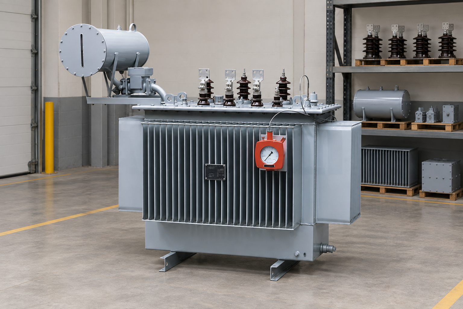
Illustrative equipment context; a clean image is not proof of a repaired asset. Reference-based illustration.
Spill control and environmental responsibilities
Assess where released oil can travel, including drains, soil, waterways and cable trenches. Use the site’s spill-response plan and the applicable environmental requirements. Avoid washing oil toward a drain or assuming that a small recurring leak has no environmental consequence.
EPA’s SPCC overview explains a United States spill-prevention framework. Its applicability and requirements depend on the facility conditions; it is not a universal rule for every country. The owner should obtain the relevant local assessment and response instructions.
Record the release, containment and disposal actions required by the site. Identify whether previous fluid contamination creates additional handling obligations. Do not infer waste classification from the word “transformer oil” alone. Use the actual material records and applicable environmental advice.
Decide repair scope before the outage
An approved repair plan should identify isolation, pressure or liquid handling, cleanliness, replacement parts, testing and restoration. For a difficult-to-access joint, it may also require lifting, temporary supply or factory support. Include those dependencies before scheduling the outage.
The owner should agree who accepts the repair and which results are required before return to service. Some repairs may need additional condition tests or observation after filling. Do not invent a universal settling time or a single test that proves every repaired transformer is ready.
A temporary measure, where specifically approved, should have a defined limitation, inspection requirement and expiry or permanent-repair plan. An undocumented sealant patch can obscure the leak source and complicate later work. The record should state what was done and the conditions under which it remains acceptable.
Return-to-service verification
Inspect the repaired area using the approved method and verify the restored fluid and preservation-system condition. Confirm that valves, accessories, temporary fittings and protective devices are in their required states. Review alarms and any tests specified by the repair engineer.
Record the final oil level with its temperature context and retain fluid-handling documents. Establish a follow-up inspection that can detect recurrence under operation. A dry surface immediately after cleaning is not equivalent to a demonstrated successful repair over the relevant operating conditions.
OSHA’s electrical work-practice reference supports the need for proper isolation and verification during electrical maintenance. Follow the applicable local rules and authorized procedure. Return to service belongs to the qualified owner and engineering process, not a visual guess.
Repair versus replacement
Compare the actual defect, broader asset condition, spare availability, outage impact and expected remaining service. A repair may be reasonable for an identifiable accessory problem in otherwise sound equipment. Extensive tank damage, repeated defects or limited support may change the comparison.
Do not infer remaining life from age alone. Review test history, loading, thermal events and maintenance evidence. Include the cost of temporary supply, fluid handling, testing and uncertainty in the decision. A low repair quotation can be incomplete if it excludes the work needed to establish safe return to service.
For a replacement inquiry, the website’s industrial oil-immersed transformer provides a relevant product category. Provide the actual site duty and requirements; do not assume that its catalog example is an exact replacement for the installed asset.
Information for specialist support
Supply the nameplate, component photographs from safe positions, leak history, oil-level and temperature records, alarms, fluid identity and maintenance history. Include the site constraints and any required temporary supply. Ask the specialist to identify missing evidence before proposing a repair.
Retain the diagnosis, approved method, parts, test results and follow-up record in the asset register. Those records help distinguish a repeat defect from a new location and support an informed replacement decision later.
Further learning
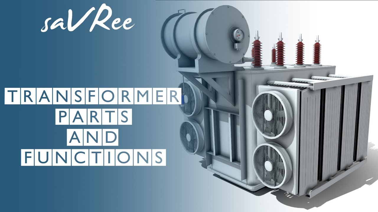
Further learning: Transformer Parts and Functions — saVRee. This educational video supports the topic; it is not a product demonstration or an operating authorization. Öffne das Video auf YouTube.
Häufig gestellte Fragen
Can a leaking transformer continue operating?
Only the owner and qualified personnel can decide from the actual condition and applicable rules. Oil level, alarms, leak development, electrical hazards and environmental consequences all matter.
Should flange bolts be tightened to stop leakage?
Do not tighten them without the approved method and specification. Incorrect torque or sequence can damage components and may not address the actual cause.
Is topping up oil a repair?
No. It replaces lost fluid under an approved procedure but does not correct the leak. Fluid compatibility, cleanliness and the underlying defect remain essential checks.
Does a dry surface prove the repair succeeded?
Not immediately after cleaning. Verify the repair under the specified conditions and complete the follow-up inspection required by the maintenance plan.
Shenheng Electric Power hat sich zum Ziel gesetzt, ein weltweiter Marktführer für Lösungen im Bereich Energieausrüstung zu werden und Kunden dabei zu helfen, ein sicheres, effizientes und nachhaltiges Energiemanagement zu erreichen.

 Shenheng Power Equipment Co., Ltd.