Shenheng Power Equipment Co., Ltd.



Switchgear busbar temperature rise is the difference between a busbar or connection temperature and the surrounding air temperature under specified operating conditions. There is no safe, universal “45°C rule” for every switchgear assembly. The allowable rise depends on the applicable equipment standard, the exact part being measured, contact and insulation materials, ambient conditions, and the manufacturer’s verified design. For medium-voltage metal-enclosed switchgear, begin with the applicable IEC 62271 requirements and the approved test report; for low-voltage assemblies, use the relevant IEC 61439 parts. A site infrared image can flag a developing problem, but it cannot replace a design temperature-rise verification or directly measure a busbar hidden behind a closed metal compartment.
Temperature rise versus absolute temperature
Temperature rise is a difference, expressed in kelvin (K); a one-kelvin difference is the same size as a one-degree-Celsius difference. Absolute temperature is the measured temperature of a component. If a verified point is 75°C while the reference ambient is 35°C, its rise is 40 K. The arithmetic is simple, but the engineering decision is not: the reading must correspond to the right location, operating current, stable thermal state and applicable limit. A warm cabinet surface is not necessarily a busbar measurement, and a cold surface does not prove that an inaccessible joint is sound.
Distinguish a factory temperature-rise test from an operational inspection. A factory test demonstrates the thermal behavior of a defined assembly configuration and loading condition. Site inspection looks for changes, asymmetry and abnormal heating in the installed equipment. It often has less access, different load and ambient conditions, and greater measurement uncertainty. Do not compare the two readings as though they were identical tests.
Which standard and which limit apply?
The first decision is the equipment class. IEC 62271-1 provides common specifications for alternating-current switchgear above 1,000 V, including temperature-rise requirements for different parts and materials; IEC 62271-200 covers AC metal-enclosed switchgear above 1 kV and up to 52 kV. By contrast, IEC 61439-1 and the relevant product part govern low-voltage switchgear and controlgear assemblies. These families are not interchangeable. A number quoted from an LV busbar table should not automatically be applied to an MV contact or a metal-enclosed compartment.
The limit also depends on what is hot. A bolted connection, contact, bare conductor, insulated conductor, terminal for an external cable and surface accessible to a person can have different criteria. Materials and coatings matter; so do the insulation system and the temperature capability of adjacent components. A procurement specification that says only “busbar rise below 45°C” leaves these distinctions unresolved. Ask the supplier to identify the standard edition, clause or table, measurement locations and test conditions supporting the proposed limit. The official IEC descriptions of IEC 62271-1, IEC 62271-200 und IEC 61439-1 establish the scope of each series; the purchased standard and approved design documents control the exact acceptance values.
| Question | Evidence to request | Warum es wichtig ist |
|---|---|---|
| MV or LV assembly? | Rated voltage and applicable IEC 62271 or IEC 61439 product standard | Different equipment families have different verification rules. |
| Which measured point? | Drawing and test-point list identifying busbar, joint, contact, terminal or accessible surface | A limit for one location must not be copied to another. |
| Which construction? | Busbar material, plating, joint design, insulation and enclosure arrangement | Heat generation and permissible temperatures depend on the complete construction. |
| Which operating condition? | Rated continuous current, loading of neighboring circuits, ambient and ventilation conditions | Thermal evidence is meaningful only for the tested duty and service environment. |
| How was it verified? | Factory temperature-rise report, calibration and measurement method | A catalog statement alone does not show how the assembly performed. |
Why a busbar or joint becomes too hot
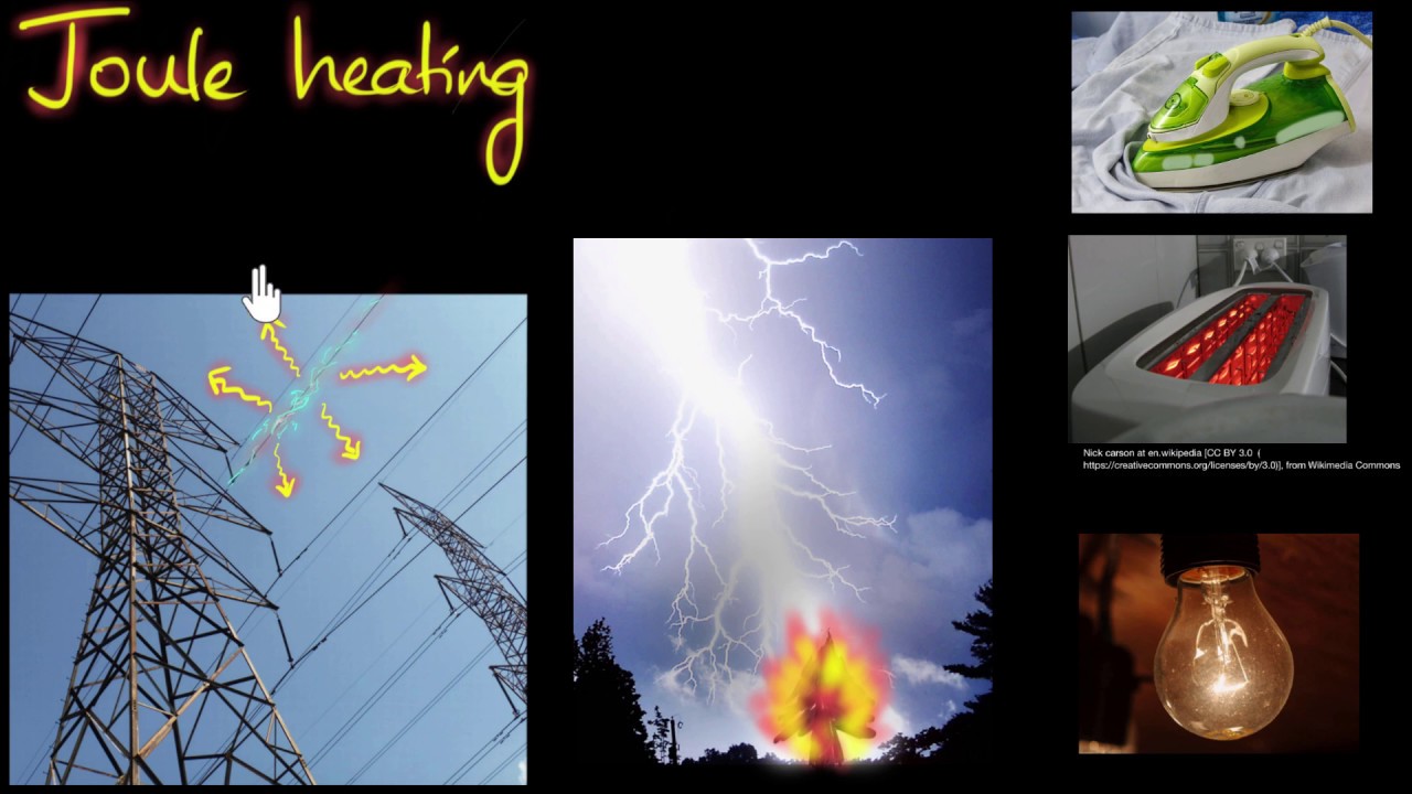
Current passing through resistance produces heat. The basic relationship is P = I²R for a resistive path: increasing current or resistance increases heat generation. This is a useful diagnostic principle, not a stand-alone temperature predictor; final temperature also depends on convection, radiation, enclosure geometry and how heat spreads to neighboring parts. The University of Colorado Boulder I²R demonstration illustrates the heating relationship. Never use the formula to infer an assembly’s permitted operating temperature without the applicable design evidence.
Current and duty
A conductor selected only by nominal ampacity can still run hotter than expected in the final enclosure. Simultaneous loading, continuous duty, adjacent heat sources and ventilation all influence the steady state. Compare actual operating current with the verified assembly rating and the permitted group loading, rather than comparing one phase to a catalog headline. Unbalanced phase currents and harmonic-rich loads can also change the thermal picture, so record representative measurements at the time of inspection.
Connections and contact condition
Loose or deteriorated joints, insufficient contact pressure, contamination, corrosion or an unsuitable interface can increase local resistance. Heating concentrated at one joint, compared with equivalent joints under similar current, deserves investigation by qualified personnel. The remedy is not to retighten an energized connection or to assume a single torque value fits every fastener: isolate the equipment, follow the approved safety procedure, and use the manufacturer’s joint design and torque instructions.
Airflow and installation environment
Restricted ventilation, blocked filters, dust, high room ambient temperature or an enclosure installed against the approved clearances can elevate internal temperatures. A row of cabinets tested with one airflow arrangement may not behave identically after field changes to cable entry plates, partitions or cooling. Record modifications and ask whether the original thermal verification still covers the as-installed arrangement.
How factory temperature-rise verification should be read
A useful factory report identifies the exact tested assembly, rated voltage and current, busbar configuration, adjacent functional units, measurement positions, ambient references, test duration and stabilization criterion. It should give both measured temperature and calculated rise, then compare each applicable location with the appropriate requirement. Review the highest point, not just an average. A report for a different cabinet depth, conductor section, joint finish or ventilation arrangement may not automatically support the offered configuration.
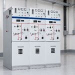
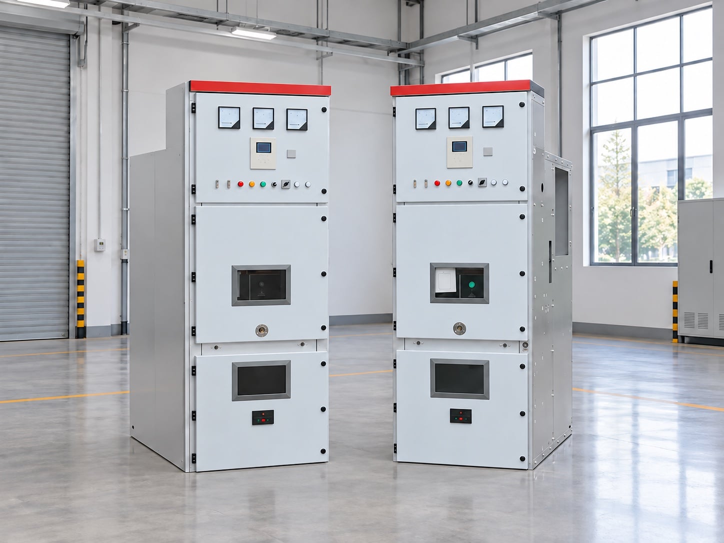
Ask whether the test represents the worst credible continuous loading of the proposed lineup. If the project adds extra outgoing feeders, uses a different busbar rating or specifies a hotter room, the supplier should explain the evidence that bridges the difference. For an RFQ, request the tested arrangement and a list of deviations rather than a broad statement that the range is “IEC compliant.” This is especially important for a KYN28-style medium-voltage switchgear lineup, where compartment geometry and the exact current path must match the project design.
Temperature-rise verification does not replace short-circuit or internal-arc evaluation. A busbar may satisfy continuous thermal duty but still require separate evidence for fault withstand. Use the short-circuit rating selection guide und internal-arc classification guide for those separate decisions.
What infrared inspection can and cannot tell you
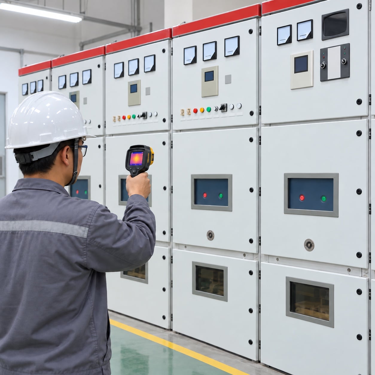
Thermography is useful for trending accessible surfaces and for comparing like-for-like points under similar load. Record current, ambient conditions, distance, view angle, emissivity assumptions, visible obstructions and the exact location of each image. A large difference between otherwise equivalent phases may indicate a problem, but the temperature contrast needs an engineering interpretation. The exterior of a closed metal cabinet is not a transparent window into the internal busbar. A cool exterior can coexist with a hot hidden joint; a warm exterior can reflect room conditions or normal heat flow.
Only trained personnel working under the site’s electrical safety program should perform inspection or open a compartment. Do not open energized equipment merely to obtain a more dramatic image or a direct busbar reading. Where inspection windows or permanently installed sensors are engineered into a verified design, follow their operating instructions and limitations. If an abnormal trend is confirmed, plan safe isolation and a condition-based investigation rather than relying on an arbitrary alarm threshold copied from another assembly.
The accompanying image shows an exterior inspection of closed switchgear. It illustrates a monitoring method, not a measured internal busbar value.
From abnormal reading to a safe decision
- Confirm context. Check load current, phase balance, operating history, ambient conditions and whether the measurement point is truly comparable to a baseline.
- Check repeatability. Reinspect the same accessible location with consistent measurement settings when safe to do so. Document instrument settings and uncertainty.
- Assess consequence. Consider whether the suspect area is a bus joint, cable termination, contact or unrelated surface; review protective device duty and any signs of damage.
- Plan isolation. If investigation requires access, follow site authorization, lockout and verification procedures. Do not use this article as a live-work instruction.
- Find the cause. Qualified personnel can inspect joint condition, contact pressure, mechanical damage, contamination and installation against approved drawings.
- Verify the repair. Retest using the manufacturer’s procedure and compare under similar loading where possible; retain the findings in the asset record.
This sequence avoids a common mistake: replacing a busbar or tightening a connection solely because one thermal photo looks bright. Color palettes are display choices, not independent evidence of an exceeded standard limit.
RFQ checklist for a thermally credible lineup
Before ordering, state the service voltage, rated continuous current, frequency, busbar current rating, short-circuit duty, number and arrangement of feeders, cable interface, room ambient and ventilation constraints. Ask the supplier to name the standards and editions used, provide the temperature-rise verification basis and mark the measured points on a drawing. Request construction details that matter thermally—conductor material and section, joint finish, insulation and enclosure configuration—without assuming the supplier uses one fixed design across all ratings.
For a comparison between offers, separate three questions: whether the proposed design is verified for the requested continuous load; whether its short-circuit and arc performance meet the project specification; and whether the offered cabinet can be installed with the required access and ventilation. A low quoted temperature number has little value if its measurement point or test arrangement does not match the proposed equipment. The broader medium-voltage switchgear selection guide covers the other procurement checks that belong alongside thermal verification.
Video: why electrical resistance creates heat
The following nonprofit Khan Academy lesson explains the heating effect of current that underlies I²R losses. It is a physics explainer, not a switchgear test procedure or a source of permitted busbar temperatures.
Häufig gestellte Fragen
Is 45°C a universal switchgear busbar temperature-rise limit?
No. It is not safe to apply one number to all busbars, contacts, terminals and voltage classes. Identify the applicable equipment standard, exact measured part, materials and verified construction before deciding whether a rise is acceptable.
Can an infrared camera measure a busbar through a closed metal door?
No. It measures radiation from the surfaces it can see. A closed metal door can be inspected as a surface, but it does not provide a direct temperature reading of the hidden busbar. Use engineered inspection access or sensors only where the approved design provides them.
Does passing a temperature-rise test prove the short-circuit rating?
No. Continuous-current heating and fault withstand are different verification questions. Review separate evidence for both.
What should I request from a switchgear supplier?
Ask for the applicable standard and edition, the tested assembly configuration, current and ambient conditions, measurement-point map, measured values and allowable limits, plus an explanation of any differences between the tested and offered designs.