Seit 2001 ist Shenheng Power ein vertrauenswürdiger Hersteller von Energieübertragungs- und -verteilungsausrüstung und liefert weltweit zuverlässige elektrotechnische Lösungen.
Unterstützt durch ein umfassendes Kundendienstsystem bieten wir kompetente technische Beratung, Produkthinweise sowie flexible OEM- und ODM-Dienstleistungen für Ihre Projekte.
Seit 2001 ist Shenheng Power ein vertrauenswürdiger Hersteller von Energieübertragungs- und -verteilungsausrüstung und liefert weltweit zuverlässige elektrotechnische Lösungen.
Prüfung des Transformator-Übersetzungsverhältnisses: Verfahren, Berechnung und Ergebnisse
Veröffentlichungszeit: 29.08.2026
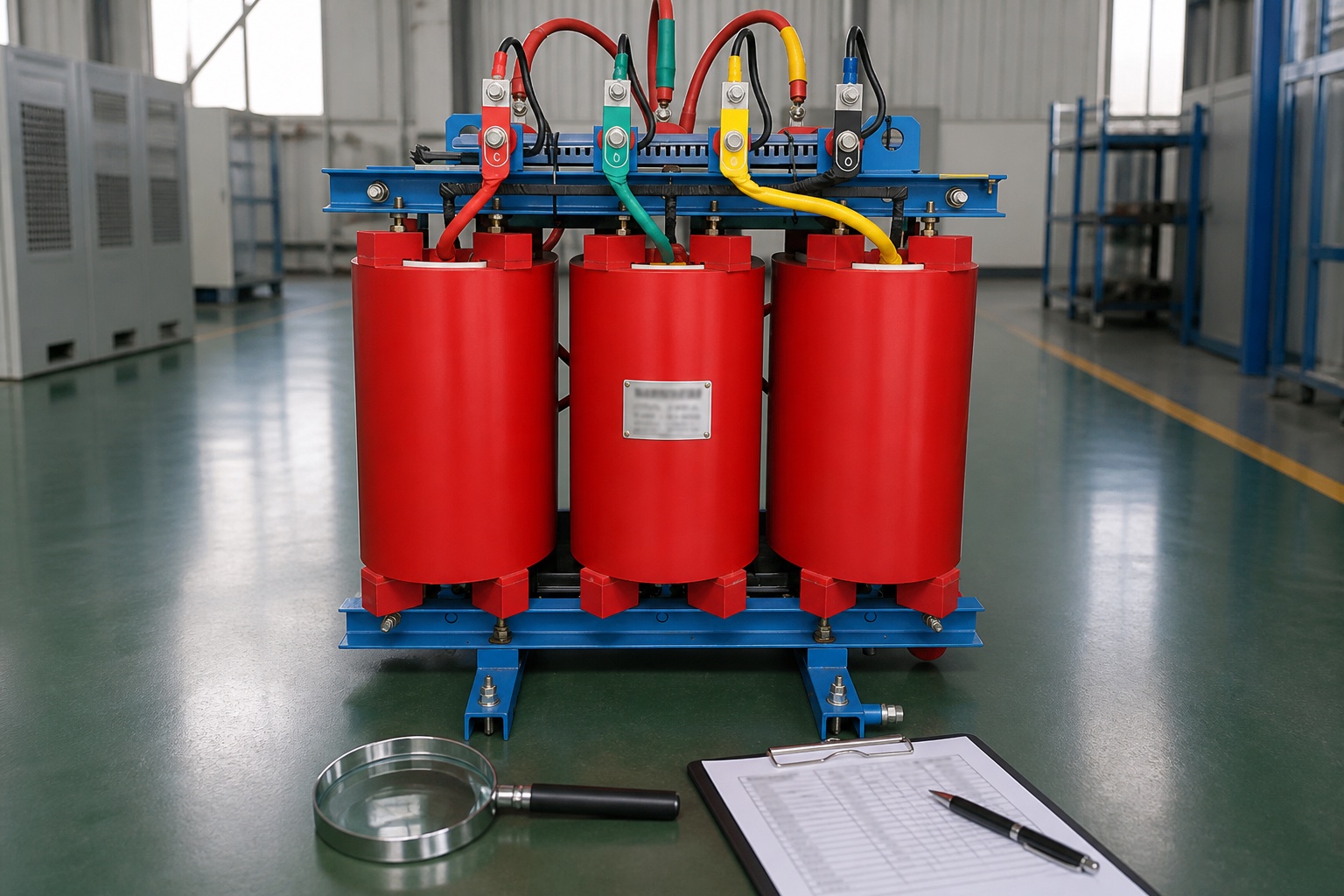
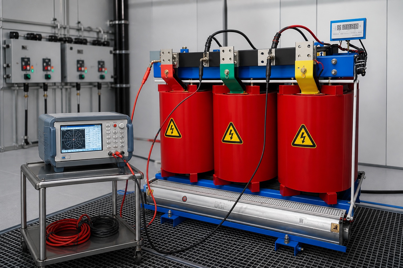
A Messung des Übersetzungsverhältnisses von Transformatoren checks whether the measured relationship between a transformer’s windings agrees with its design and nameplate connection. A test set applies a controlled low AC voltage to one winding, measures the induced voltage on another winding, and reports the ratio, phase relationship, and often excitation current. The test can reveal incorrect tap position, connection errors, open circuits, and some winding defects, but it cannot diagnose every internal problem by itself. The transformer must be isolated, de-energized, discharged, and tested by qualified personnel using the approved procedure for the specific unit.
What a transformer turns ratio test verifies
The fundamental voltage relationship of an ideal transformer follows the winding relationship:
VH / VL = NH / NL
Here, V is voltage and N is the number of turns; H and L identify the higher- and lower-voltage windings. A field instrument does not count turns. It measures voltage ratio under a small test excitation and compares the result with the ratio expected from the nameplate voltages, tap position, winding configuration, and vector group.
The test is valuable during factory acceptance, commissioning, post-transport inspection, troubleshooting, and condition-based maintenance. Ratio testing can help identify a changed winding relationship by comparing field results with nameplate, factory, and previous data. The result should be interpreted with other evidence, not used as a stand-alone verdict.
Record the complete nameplate, vector group, rated voltages, and tap position before comparing a measured ratio.
When project teams use TTR testing
A baseline result taken before energization gives the owner a reference for future comparison. Testing is especially useful after delivery because impact, loose internal connections, or an incorrect external reconnection may not be obvious during a visual inspection. It is also commonly included after major repair, tap-changer work, protection operation, or an abnormal event.
For a new transformer, the test record should identify the serial number, test instrument, calibration status, winding temperature or ambient condition when relevant, test voltage, tap position, connection mode, measured ratio, expected ratio, deviation, excitation current, and phase-angle or vector-group result. That record is more useful than a simple “pass” statement because it supports trend comparison and engineering review.
Project stage
What the ratio test can check
What should accompany it
Factory or pre-shipment
Design ratio, winding connection, tap sequence
Routine test report and approved nameplate data
Site commissioning
Shipping condition, terminal reconnection, tap position
Visual inspection, insulation tests, grounding and protection checks
After maintenance
Correct reconnection and tap-changer work
Work scope, previous baseline, manufacturer instructions
Troubleshooting
Abnormal ratio, phase relation, or excitation-current pattern
Insulation, winding resistance, oil or thermal evidence as applicable
Information required before connecting the test set
Start with the approved transformer documents rather than guessing from terminal positions. Obtain the nameplate photograph, single-line diagram, winding diagram, vector group, rated primary and secondary voltages, frequency, available taps, neutral arrangement, and manufacturer test report. Confirm whether the equipment is a two-winding, three-winding, autotransformer, single-phase, or three-phase design.
Tap position matters. An off-circuit or on-load tap changer deliberately changes the effective winding ratio. A result compared against the wrong tap reference can appear defective even when the transformer is correct. Record both the mechanical indication and the electrical position available to the test procedure.
Three-phase connections also affect the relationship between line and phase voltage. Delta, wye, zigzag, and phase displacement cannot be ignored. Modern three-phase test sets can evaluate phases and vector relationships automatically, but the operator must still enter the correct configuration. For terminal marking and connection conventions, refer to IEEE C57.12.70. The applicable contract standard and manufacturer data govern the actual acceptance decision.
Safe transformer turns ratio test procedure
This overview is for planning and review, not a substitute for an approved method statement. Testing should be performed by qualified personnel within the site electrical-safety program.
Identify and isolate the transformer. Verify the correct asset and all possible sources, including backfeed from secondary systems, tertiary windings, station service, generators, and connected cables.
Establish an electrically safe work condition. Apply the facility’s lockout/tagout process, verify absence of voltage with a suitable instrument, discharge stored energy, and install protective grounds where the approved procedure requires them. OSHA’s control of hazardous energy guidance explains the basis of lockout/tagout programs.
Inspect and document. Note terminal condition, contamination, damage, grounding, tap indication, and nameplate details. Do not proceed if the equipment identity or connection is uncertain.
Disconnect circuits when required. Connected cables, surge arresters, potential transformers, or other components can influence the setup or expose equipment to unintended test voltage. Follow the manufacturer and test-set instructions.
Connect leads to the designated windings. Keep leads organized, secure, and clear of grounded metal. Confirm phase labels before applying test voltage.
Select the correct test object configuration. Enter rated voltages, winding connection, vector group, frequency, phase, and tap position. An incorrect setup produces misleading results.
Run the sequence on every required tap. Observe ratio, deviation, excitation current, and phase relation. Stop if readings are unstable or inconsistent with the expected connection.
Save raw results and restore the transformer. Remove test leads, return temporary disconnections and taps to the approved state, perform an independent check, and update the commissioning record.
Ratio results should be reviewed with other transformer tests and the approved factory baseline.
How to calculate ratio deviation
Many instruments calculate deviation automatically. For an engineering check:
Deviation (%) = (Measured ratio − Expected ratio) / Expected ratio × 100
Suppose the expected ratio for the selected tap is 20.000 and the instrument reports 20.060. The deviation is (20.060 − 20.000) / 20.000 × 100 = 0.30%. This arithmetic does not by itself determine acceptance. The correct expected ratio must reflect the actual winding connection and tap position, and the result must be judged against the applicable standard, manufacturer limits, factory report, instrument uncertainty, and project specification.
The current edition of IEEE C57.152 describes field diagnostic testing of liquid-filled power transformers and stresses combined interpretation of diagnostic results. Dry-type and special transformers may be governed by different standards and manufacturer procedures.
Interpreting patterns instead of one number
Similar deviation on all phases
A consistent offset may point to the wrong expected ratio, incorrect tap reference, a data-entry error, or a systematic connection issue. Confirm the nameplate voltages and whether the software expects line-to-line or phase values before assuming an internal defect.
One phase differs from the others
A phase-specific difference deserves investigation. Possible causes include poor lead contact, mislabeled terminals, an open or damaged winding connection, tap-changer contact problems, or winding damage. Repeat the test only after checking the setup; do not repeatedly energize a questionable test circuit without understanding the abnormality.
Ratio changes irregularly across taps
A smooth, expected progression is normally anticipated across tap positions. A discontinuity may indicate an incorrect mechanical indication, connection problem, or tap-changer issue. Compare the sequence with factory data and the tap-changer diagram.
Abnormal excitation current
Excitation current is sensitive to test voltage, connection, core condition, residual magnetism, and instrument method. It can support diagnosis, but it should not be interpreted without phase comparison, previous readings, and the test-set guidance.
Häufige Testfehler
Comparing a field result with the nominal ratio instead of the expected ratio for the actual tap.
Entering the wrong vector group or winding connection.
Leaving external circuits connected without checking their effect.
Using poor, contaminated, or mislabeled lead connections.
Recording only a pass/fail label and losing phase-by-phase raw data.
Applying one universal tolerance to every transformer and test purpose.
Treating a satisfactory TTR result as proof that insulation, core, bushings, and all mechanical parts are healthy.
How TTR fits into transformer commissioning
Ratio testing is one part of a coordinated commissioning package. The final scope may include insulation resistance, winding resistance, excitation current, power factor or dissipation factor, core ground checks, fluid tests for liquid-filled units, functional checks of alarms and cooling, protection testing, and verification of grounding and phase rotation. The exact combination depends on transformer type, voltage class, contract, applicable standard, and manufacturer instructions.
Procurement teams can reduce site uncertainty by requesting factory ratio results for every tap and ensuring that nameplate, vector group, and terminal diagrams are approved before shipment. Shenheng’s guide to transformer nameplate ratings helps teams identify the information needed for comparison, while the article on Transformatorimpedanz und Parallelbetrieb explains a separate parameter that TTR does not verify.
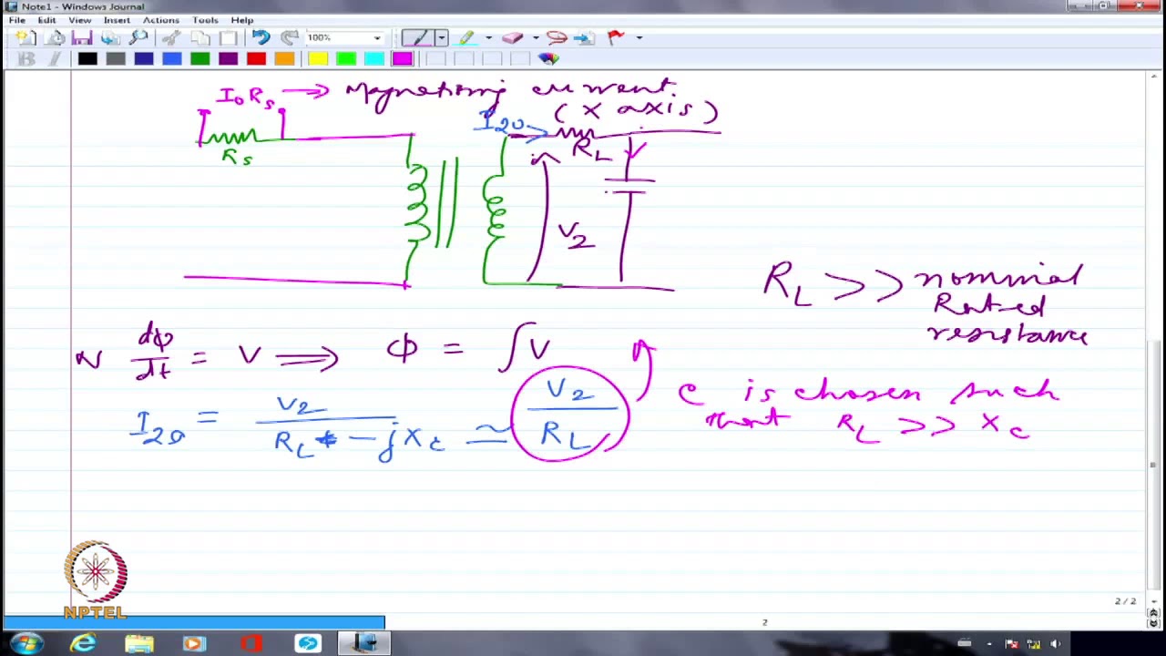
The following NPTEL IIT Delhi lecture explains the voltage and circuit relationships behind transformer measurements. It provides theory; it does not replace site safety rules or the test-set manual.
Transformer turns ratio test FAQ
Does a TTR test require the transformer to be de-energized?
Conventional field TTR testing is performed with the transformer isolated and de-energized. All sources and possible backfeeds must be controlled under the approved safety procedure.
Can a turns ratio test find every shorted turn?
No. It may reveal ratio changes associated with winding problems, but sensitivity depends on the defect, transformer design, connection, and method. Results should be combined with other diagnostic evidence.
Should every tap be tested?
Commissioning and post-maintenance programs commonly require the specified tap sequence because it checks both ratio progression and tap-changer connections. Follow the project and manufacturer procedure.
Is voltage ratio always identical to physical turns ratio?
The ideal relationship is proportional, but three-phase line/phase relationships, connection groups, taps, measurement method, and real losses must be handled correctly when calculating the expected field result.
What should be included in a TTR report?
Include asset identity, nameplate data, vector group, taps, instrument and calibration details, test voltage, phase-by-phase results, deviation, excitation current when measured, observations, acceptance basis, and reviewer approval.
Shenheng Electric Power hat sich zum Ziel gesetzt, ein weltweiter Marktführer für Lösungen im Bereich Energieausrüstung zu werden und Kunden dabei zu helfen, ein sicheres, effizientes und nachhaltiges Energiemanagement zu erreichen.

 Shenheng Power Equipment Co., Ltd.