Transformer Zero Sequence Impedance Measurement: Report Guide
Release Time: 2026-10-30
Transformer zero sequence impedance measurement establishes the voltage-current relationship for a specified zero sequence test arrangement. The result helps engineers represent earth fault behavior, but its meaning depends on winding connection, neutral availability, magnetic construction and the condition of other windings during measurement. A useful report names the terminals, grounding arrangement, test frequency, applied conditions and result basis. A single percentage labeled impedance is insufficient. Zero sequence impedance must not be substituted automatically for the positive sequence short circuit impedance shown on a normal transformer data sheet.
This guide is for reviewing test specifications and reports. It is not a wiring procedure. Test connections, neutral handling and applied voltage require qualified personnel working to an approved method for the particular transformer.
Why zero sequence requires its own question
Sequence networks describe different system conditions. A balanced positive sequence operating or short circuit model does not automatically describe the paths available to zero sequence current. The winding connections and external neutral arrangement determine whether current can enter the relevant terminals at all.
Research published through the Universidad Carlos III de Madrid research portal examines rules for estimating zero sequence impedance in three phase core type transformers. It illustrates why construction and configuration matter. An estimation rule from a particular study is not a replacement for the equipment-specific measurement or agreed model.
Start by writing down the engineering decision: an earth fault study, a neutral equipment assessment or validation of supplied network data. The intended use determines the required result basis and supporting information. Without that decision, a detailed test certificate may still provide the wrong input for the system model.
Identify the winding and neutral arrangement
State the vector group, accessible terminals and neutral connections in the request. A neutral brought out at the transformer and a neutral actually connected in the installed system are separate facts. The report should make clear which arrangement was measured and which arrangement the network study assumes.
Record whether other windings were open, shorted, connected in delta or otherwise configured under the approved method. A delta path can affect zero sequence behavior even when external line currents do not flow in that winding in the same way. The specialist should explain the relevant arrangement rather than reducing the result to the transformer’s power rating.
Do not assume that a result for one side of the transformer can be copied directly to the other without conversion and configuration review. The reference winding, voltage basis and measurement arrangement must remain attached to the value whenever it is transferred into a study file.
Required report item
Why the engineer needs it
Common review error
Tested winding and terminals
Defines the observed network port
Using a result on the wrong winding basis
Neutral and other winding conditions
Defines available current paths
Assuming all connection arrangements are equivalent
Frequency and excitation conditions
Supports assessment of measurement applicability
Ignoring the conditions behind a single value
Units and reference base
Allows correct transfer to the system model
Mixing ohms, percent and per unit
Construction and limitations
Supports interpretation of magnetic return paths
Treating a generic estimate as a measured certificate
The table is a documentation checklist. The approved test method must define the actual connection and operating conditions; this guide intentionally provides no field connection diagram.
Conceptual illustration of linking a test report to its stated winding arrangement.
Keep construction information with the result
Core construction and magnetic return paths influence zero sequence behavior. A three limb core, other core arrangements and shell type constructions should not be assumed to behave identically. Ask the manufacturer to identify the construction information needed for the model rather than guessing from the external tank shape.
The transformer tank and surrounding structures may be relevant to the magnetic response under particular conditions. That is another reason a nameplate short circuit impedance cannot universally stand in for zero sequence data. The responsible specialist should determine the appropriate representation for the equipment and study.
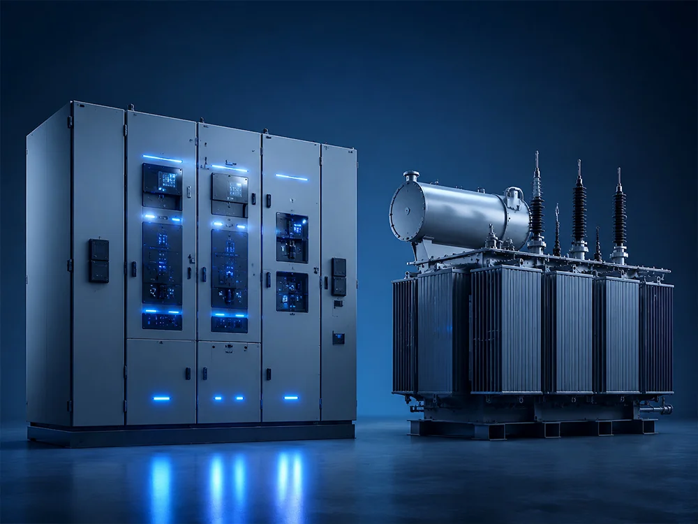
A photograph can confirm visible product identity but cannot establish the internal magnetic circuit. Keep drawings, declared construction data or the manufacturer’s written explanation as the evidence for internal design statements. Do not infer the core arrangement solely from the number of external radiators or bushings.
Understand the reported numerical basis
A result may be expressed in ohms, percent or per unit on a stated base. Preserve that base, reference winding and frequency. A number separated from those qualifiers is easy to enter incorrectly into a short circuit program, particularly when equipment data comes from several suppliers.
For a three phase base, engineers commonly use base impedance equal to the square of base line-to-line voltage divided by base three phase apparent power, with consistent units. This is a base conversion relationship, not a substitute for the test method’s definition of measured zero sequence impedance. Confirm how the laboratory converted its terminal measurements before applying any further conversion.
As an illustrative unit check, a base of 10 kV and 10 MVA gives 10 ohms. A value of 0.2 per unit on that same base corresponds to 2 ohms. These invented inputs explain conversion only; they are not a Shenheng specification, a typical zero sequence value or an acceptance criterion.
Review excitation and comparability
Ask whether the reported result changes with the applied test conditions and whether the selected point represents the intended study use. Magnetic behavior can make a single number an incomplete description. If the manufacturer supplies a characteristic or several measurements, retain the supporting conditions with each point.
For repeat measurements, compare connections, frequency, tap position where relevant, test equipment and the state of other windings. A difference between reports may reflect a changed arrangement rather than a changed transformer. Resolve those differences before labeling a result abnormal.
The public scope of IEC 60076-1 gives the general power transformer standards context. The applicable edition, contract and agreed test procedure must determine the required measurement and reporting details. A standards citation alone is not evidence that a particular terminal arrangement was tested correctly.
Use the result in an earth fault model carefully
Transformer zero sequence data is one component of the full system model. Source impedance, grounding arrangement and any neutral impedance also matter. Keep these elements separate so that a neutral resistor is not accidentally included twice or omitted when importing supplier data.
الوجود الحالي transformer impedance and fault level guide addresses the broader impedance question. The zero sequence measurement adds configuration-specific information rather than replacing the positive sequence data needed for other calculations.
Record whether the study uses a measured value, a manufacturer estimate or an engineering assumption. These are different evidence states. When measured data is unavailable, the engineer may choose a justified assumption and sensitivity study, but the assumption must remain visible in the issued calculation.
Keep units, reference base and grounding assumptions visible in the network study.
Investigate an unexpected result methodically
First verify equipment identity and report transcription. Confirm the side, base and decimal convention before requesting a repeat test. A percent value entered as per unit creates a substantial modeling error even when the original laboratory measurement was sound.
Then compare the actual test arrangement with the requested one. Ask the test specialist about neutral connection, other winding conditions and any restrictions observed during measurement. Retain the original report and issue a documented clarification rather than silently changing the study input.
Finally evaluate the system consequence with the responsible protection or power system engineer. A changed input may affect an earth fault calculation, but its effect depends on the complete network. Do not adjust protection settings or grounding equipment from an isolated certificate without the required system review.
Include the intended study, reference winding, required units, connection documentation and acceptance basis in the technical exchange. The commissioning record should retain the final accepted data and any unresolved assumptions for the operating team.
Close the handover by confirming that the test report and the model use the same basis. A second reviewer should be able to trace the input from supplier evidence to the issued calculation without reconstructing undocumented conversions. That traceability is more valuable than a certificate containing a single unexplained percentage.
When data is supplied in a spreadsheet, verify that the column heading identifies the sequence and winding basis. A field named only impedance invites accidental reuse in a different calculation. Keep the original certificate linked to the data row and record who approved any conversion. If software requires resistance and reactance separately but the report provides only a magnitude, request clarification rather than inventing a split. The model should preserve the limits of the evidence even when the software form encourages a more detailed input.
A separate insulation resistance record addresses insulation resistance rather than sequence network parameters. Keep the purpose of each measurement clear in the handover so that a satisfactory result from one test is not substituted for missing evidence from another.
التعلم المستمر
The NPTEL lecture on sequence networks explains the power system modeling background. It is educational context, not a zero sequence test connection instruction or evidence of a measured Shenheng value.

 شركة شنغهنغ لعدات الطاقة المحدودة.