نظام التأريض في المحطات الفرعية: تصميم الشبكة، جهد اللمس، والاختبار
وقت الإصدار: 2026-08-31
A نظام تأريض المحطة الفرعية هي شبكة مترابطة من الموصلات المدفونة، وقضبان التأريض أو الأقطاب الكهربائية، ووصلات التوصيل بين المعدات، والهياكل، والأسوار، والأسلاك المحايدة، وأغلفة الكابلات، والمعالجة السطحية؛ والتي توفر مسارًا خاضعًا للرقابة لتيار الأعطال والبرق، مع الحد في الوقت نفسه من جهد اللمس وجهد الخطوة الخطيرين. لا تتحقق التأريض الجيد بمجرد السعي وراء رقم واحد للمقاومة المنخفضة. يجب أن يأخذ التصميم في الاعتبار الحد الأقصى لتيار الشبكة، ومدة العطل، ومقاومة التربة وطبقاتها، والحمل الحراري للموصلات، وهندسة الشبكة، والجهد المنقول، وتعرض الإنسان، والتآكل، ومسافة الحماية. يلزم إجراء دراسة تأريض مؤهلة والالتزام بالمعايير التي تحكم المشروع قبل البدء في البناء.
ما يجب أن تحققه شبكة التأريض
أثناء حدوث قُصْر أرضي، يدخل التيار في نظام التأريض ويرفع شبكة المحطة الفرعية فوق الأرض البعيدة. هذا الارتفاع في جهد الشبكة أمر لا مفر منه؛ وتتمثل مهمة السلامة في إبقاء فروق الجهد التي يمكن لشخص أن يجتازها ضمن معايير التصميم وضمان بقاء الموصلات سليمة خلال الحدث. إن ربط الأجزاء الموصلة المكشوفة يبقيها قريبة من جهد مشترك، بينما تعمل الهندسة المدفونة والمواد السطحية على تشكيل تدرج الجهد.
معيار معهد مهندسي الكهرباء والإلكترونيات 80 يوفر إرشادات للسلامة في تأريض محطات التحويل الفرعية للتيار المتردد. يجب التأكد من الإصدار الحالي والمتطلبات المحلية لكل مشروع. قد تستخدم المشاريع القائمة على معايير اللجنة الكهرتقنية الدولية (IEC) طرقاً أخرى. إن تباعد الشبكة المنسوخ أو قاعدة مثل “ قضيب واحد في كل ركن” لا يعد تصميماً.
يجب اعتبار المحولات، ومعدات التوزيع، والهعياكل، وأنظمة الكابلات، والأسوار، ومباني التحكم كمنظومة تأريض واحدة.
الأجزاء الرئيسية لنظام تأريض المحطة الفرعية
عنصر
الغرض الأساسي
موجب للقلق التصميمي
موصِلات الشبكة المدفونة
توزيع متجهات التدرج الحالية وسطح التحكم
الهندسة، العمق، الحمل الحراري، التآكل
قضبان التأريض / الأقطاب الكهربائية
الوصول إلى تربة أعمق وتكملة الانتشار الحالي
طبقات التربة، التباعد، أضرار التركيب
سندات المعدات
وصل الخزانات، والإطارات، والخزائن، والهياكل، والمحايدات
مسارات قصيرة وموثوقة ومفاصل سهلة الوصول
سندات الأسوار والبوابات
التحكم في جهود المحيط القابل للوصول إليها
الفولتية المنقولة والمفاصل المتحركة
الطبقة السطحية
زيادة مقاومة ملامسة القدم
المقاومة النوعية للمادة، والسماكة، والرطوبة، والصيانة
الاتصالات
الحفاظ على استمرارية الشبكة
واجب الخلل، تآكل، صناعة، تفتيش
المدخلات المطلوبة لدراسة التأريض
نموذج مقاومة التربة
قس مقاومة التربة عبر مسافات مناسبة بين المسابر ومواقع مختلفة في الموقع. قراءة واحدة لا يمكنها وصف التربة الطبقية، أو الصخرية، أو المدموكة بالردم، أو الرطبة، أو المتغيرة موسمياً. تحول الدراسة بيانات الحقل إلى نموذج للتربة وتسجل نسبة عدم اليقين. القياسات التي تُجرى بعد استيراد ردم موصل للكهرباء أو أثناء حالة رطوبة غير معتادة قد لا تمثل الموقع النهائي.
تيار العطل ووقت المقاطعة
حساب تيار الشبكة ليس ببساطة تصنيف قاطع الدائرة للتيار الصغير. فهو يأخذ في الاعتبار جزء تيار الخطأ الأرضي الدخل إلى الشبكة، ومسارات العودة عبر أسلاك الدرع العلوية، والنقاط المحايدة، وأغلفة الكابلات، وأنظمة التأريض المجاورة، وموقع الخطأ. يؤثر وقت إزالة الحماية على تسخين الموصل والتعرض المسموح به. استخدم دراسات قصر الدائرة والحماية المعتمدة.
هندسة الموقع والتعرض
توفير السياج، والبوابات، والطرق، ومبنى التحكم، وأساسات المعدات، وخنادق الكابلات، والسكك الحديدية، خطوط الأنابيب، ومسارات الاتصالات، والخطوط القادمة، والمباني المجاورة، ومناطق الوصول العام. إن التعرض لجهد اللمس والخطوة عند المحيط يمكن أن يتحكم في التصميم حتى لو كانت القيم بالقرب من المعدات الرئيسية مقبولة.
اللمس، والخطوة، والشبك، والجهد المنقول
جهد اللمس فرق الجهد الذي يمكن للشخص ربطه بين جسم مؤرض والسطح الذي تحته القدمان. جهد الخطوة هو الفارق السطحي بين قدمين. جهد الشبكة هو جهد لمس محسوب داخل شبكة أرضية. جهد منقول يحدث عندما يحمل موصل أو درع أو أنبوب أو قضبان أو خط محايد جهد المحطة الفرعية إلى موقع آخر - أو ينقل جهداً عن بُعد إلى داخل الساحة.
تتطلب الجهود المنقولة مراجعة الواجهة، وليس فقط حساب الشبكة المحلية. يمكن لأنابيب المياه المعدنية، ودروع كابلات الاتصالات، والموصلات المحايدة ذات الجهد المنخفض، وتمديدات السياج، واللوحات البعيدة أن تخلق مسارات غير متوقعة. يجب هندسة تدابير العزل، أو الربط، أو الحماية من زيادة التيار، أو التحكم في التدرج للنظام الفعلي.
عملية التصميم
تعريف الموقع، والمعايير الحاكمة، ومعايير السلامة، وسيناريوهات الأعطال، والمناطق التي يمكن الوصول إليها.
قياس مقاومة التربة وتطوير نموذج التربة المبرر.
تحديد تيار الشبكة وقت التفريغ من دراسات النظام.
اختيار مادة وحجم الموصل لتلبية متطلبات الأداء الحراري، الميكانيكي، المقاومة للتآكل، والعمر التشغيلي.
إنشاء هندسة شبكية أولية حول المعدات والهياكل والسياج ومواقع التشغيل.
Model grid-potential rise and touch, step, and mesh voltages.
Revise conductor spacing, rods, perimeter control, surface material, and bonds where criteria are not met.
Issue coordinated construction drawings, connection details, material specifications, and inspection points.
Verify the installed system before burial and perform the specified commissioning tests.
Equipment bonding details
Transformer tanks, radiators where required, marshalling kiosks, switchgear frames, operating handles, cable boxes, surge arresters, steel structures, control-building steel, metallic cable trays, fences, gates, and auxiliary systems need defined bonds. A single daisy chain can make downstream equipment dependent on one joint; critical items may require two independent connections to different grid points.
Neutral grounding connections carry system current under specific faults and must not be treated as ordinary equipment bonds. Their route, CT position, parallel paths, and connection to the grid affect protection. Coordinate transformer neutral, grounding resistor or reactor, station service, and LV neutral arrangements with the protection study.
Compact substations still require coordinated bonds for the enclosure, transformer, switchgear, cable shields, neutral, and external site earth.
Construction quality before backfilling
The buried grid becomes difficult to inspect once civil works advance. Establish hold points for conductor depth and routing, connection method, rod installation, foundation interfaces, riser locations, material compatibility, and photographic records. Protect conductors from concrete-work and excavation damage. Keep connections clean and make them with the qualified process.
Update as-built coordinates when the route changes around foundations or services. A drawing that shows the design but not field deviations weakens future testing and excavation safety. Record every accessible test point and equipment bond label.
Commissioning and condition assessment
Commissioning may include visual inspection, continuity testing of the grid and equipment bonds, verification of conductor routing before burial, soil or system measurements, and specialized integrity testing. A simple clamp measurement at one bond does not prove the safety of the entire grid. Test methods, limits, current injection, remote probes, and interpretation depend on the system and standard.
EPRI has researched substation ground-grid condition assessment, reflecting the difficulty of evaluating buried systems. During service, inspect corrosion, broken flexible gate bonds, construction damage, added equipment without bonds, loose accessible joints, fence changes, and civil modifications. Revisit the study when fault levels, clearing times, footprint, soil, or connected metallic systems materially change.
Interpreting measurements responsibly
Test results depend on current paths, probe placement, connected neutrals and shields, soil condition, interference, and instrument method. Compare readings with the study model and earlier tests made under similar conditions. An unexpected value should trigger a setup and grid-configuration review before excavation. Conversely, one satisfactory overall resistance measurement cannot close a defect involving a broken equipment bond or unsafe perimeter gradient.
Grounding and worker safety
A permanent ground grid does not eliminate the need for isolation, absence-of-voltage verification, and temporary protective grounding during work. It also does not guarantee zero voltage during faults. OSHA’s موارد السلامة الكهربائية provide regulatory context in the United States. Switching, equipotential work zones, induced voltage, and temporary grounds require site-specific procedures.
Common grounding mistakes
Using ground resistance as the only acceptance measure.
Assuming uniform soil without adequate field measurements.
Using equipment fault rating as grid current without current-split analysis.
Ignoring the fence, gate, remote panels, pipes, cable shields, and LV neutrals.
Changing conductor routes during civil work without engineering review.
Burying connections before inspection and photographic evidence.
Adding equipment later without updating bonds and the grounding study.
Assuming a surface stone layer permanently retains its original electrical properties.
Grounding information for packaged substations
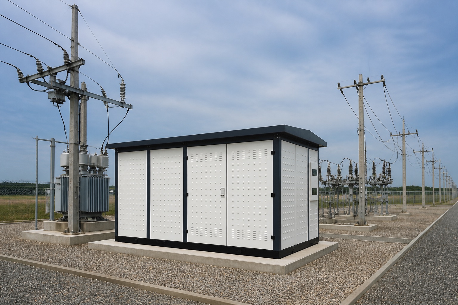
For a prefabricated or compact substation, the vendor should identify enclosure bonding points, transformer tank bonds, MV/LV switchgear bonds, neutral connection, cable-shield connections, internal conductor size, and interface to the external grid. The project engineer remains responsible for integrating the package into the site grounding study.
This independent educational video illustrates grounding, step potential, and touch potential. It is conceptual and does not replace a grounding study.
حدود القبول The finished grounding system should be accepted against the engineered study, approved drawings, material and connection requirements, construction inspections, as-built record, and specified tests. A generic target copied from another substation cannot account for this site’s soil, fault-current split, clearing time, accessible areas, or transferred potentials. Unresolved departures require engineering disposition before energization.
Substation grounding system FAQ
ما هي المقاومة الأرضية الجيدة للمحطة الفرعية؟
لا توجد قيمة مقاومة واحدة تثبت الأمان. يجب أن يلبي التصميم متطلبات اللمس، والخطوة، والحرارة، ومتطلبات المشروع لظروف العطل والتربة الفعلية.
لماذا يتم استخدام الحجر المكسور في المحطات الفرعية؟
A suitable high-resistivity surface layer can increase foot-contact resistance and reduce body current, but material properties, thickness, moisture, contamination, and maintenance matter.
هل يحتاج كل عنصر إلى توصيلين أرضيين؟
Requirements depend on the item, standard, owner practice, and reliability objective. Major equipment often uses multiple deliberate paths; drawings must define them.
متى يجب تحديث دراسة التأريض؟
قم بتحديثه عندما تتغير تيار العطل، أو وقت المقاطعة، أو هندسة الموقع، أو المعدات، أو السياج، أو ظروف التربة، أو الأنظمة المعدنية المتصلة بشكل جوهري.
هل يمكن لاختبار الاستمرارية إثبات أن الشبكة آمنة؟
No. It verifies selected conductive paths but does not alone prove soil performance, current distribution, or acceptable touch and step voltages.

 شركة شنغهنغ لعدات الطاقة المحدودة.