مبدأ عمل وحدة الحلقة الرئيسية (RMU): تدفق الطاقة، وعزل الأعطال، والاستعادة
Release Time: 2026-08-31
ال مبدأ عمل وحدة الحلقة الرئيسية is based on sectionalizing a medium-voltage cable ring while supplying a local transformer or feeder from one compact switchgear assembly. Two ring switches normally connect the incoming and outgoing cable sections, and a third way feeds or protects the transformer. With both healthy ring paths available, the network can be operated as a closed ring or, more commonly in distribution practice, as an open ring with a designated normally open point. After a cable fault is identified and isolated, operators can restore healthy sections from the alternate direction, subject to ratings, protection, interlocks, and the utility switching plan.
What an RMU does
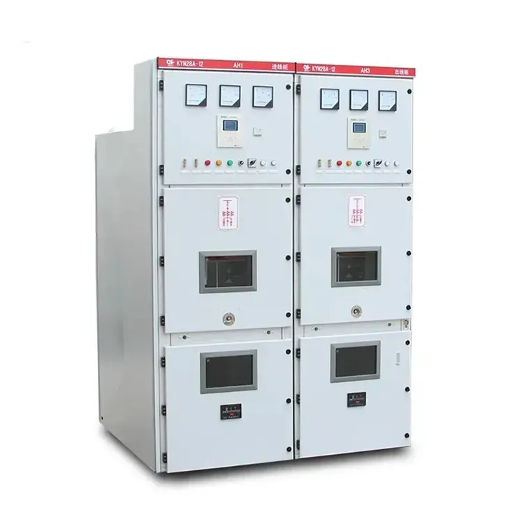
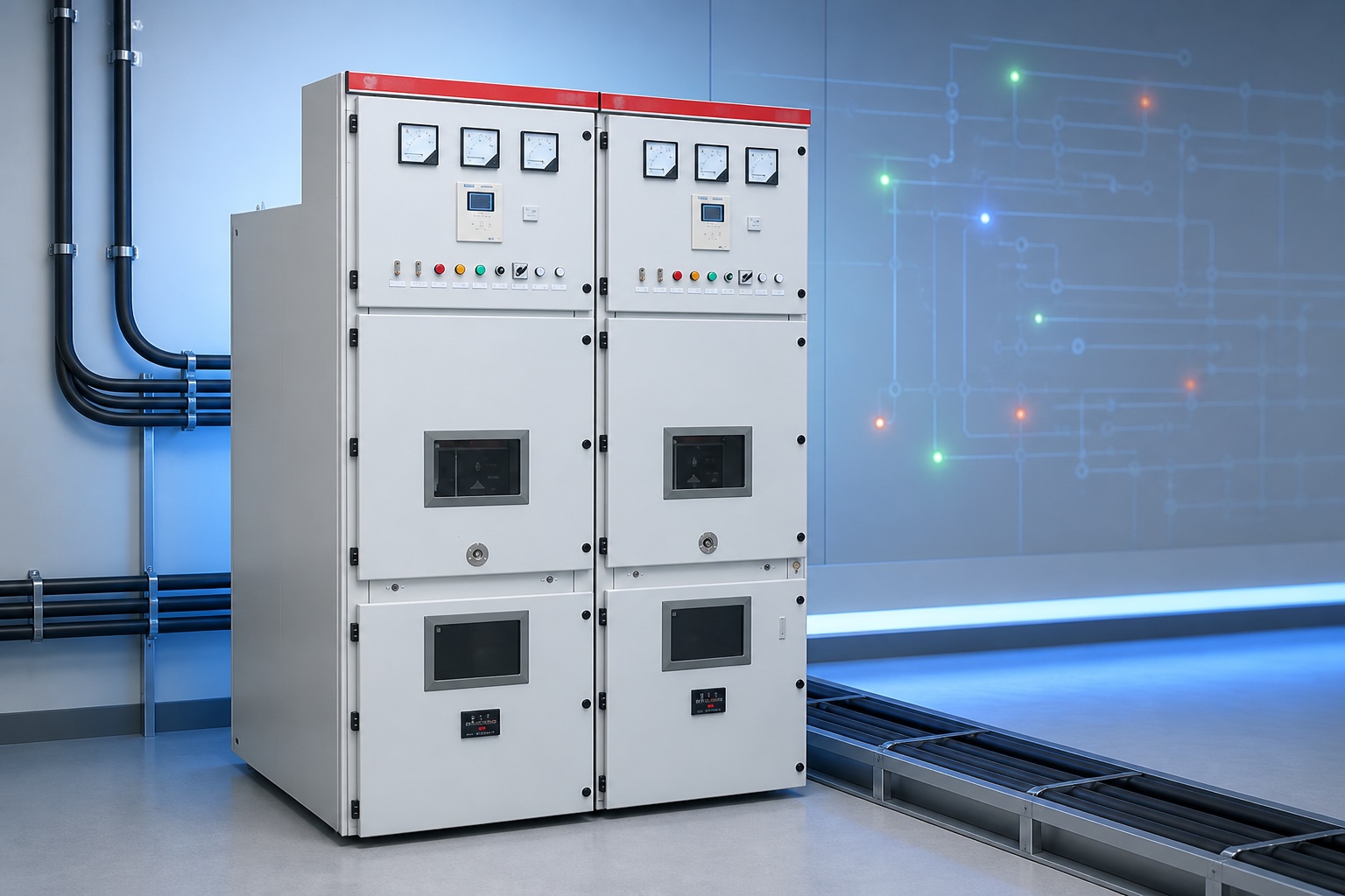
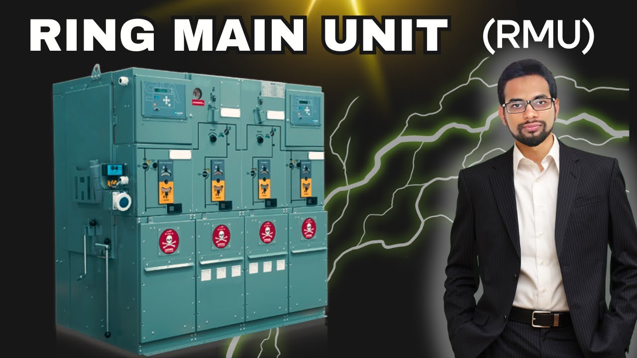
A ring main unit is metal-enclosed medium-voltage switchgear designed for compact secondary distribution. It provides switching, isolation, earthing, and—in the transformer way—fuse-switch or circuit-breaker protection. The enclosure may use air, solid material, or gas insulation depending on design. “RMU” describes the network function and arrangement; it does not by itself define the interrupting device, insulation medium, internal-arc classification, voltage rating, or automation level.
IEC 62271-200 addresses AC metal-enclosed switchgear and controlgear above 1 kV and up to 52 kV. Refer to the IEC publication page and use the project-specified edition. Product selection must also comply with the local utility rules and system study.
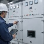
Typical RMUs combine two cable-ring ways with a protected transformer or feeder way in a compact lineup.
Typical functional ways
Functional way
Normal role
Important selection question
Incoming ring switch
Connects one side of the cable ring
Load-break and fault-making duties
Outgoing ring switch
Continues the ring to the next station
Cable rating, earthing, and test access
Transformer fuse-switch
Switches load and coordinates fuses for transformer faults
Fuse coordination and transformer inrush
Transformer circuit breaker
Trips through relay protection
Fault duty, CTs, relay, and trip supply
Metering or automation way
Measures and supports remote control
Sensor accuracy, communications, and cybersecurity
How power flows through an open ring
Imagine substations A, B, C, and D connected by a cable loop from two source points. A normally open point prevents uncontrolled parallel flow between sources. Each station remains energized from one direction. The two ring switches in an RMU carry the cable path, while the transformer way taps power to the local low-voltage network.
If the cable between B and C fails, protection first removes fault current according to the network design. Operators then prove the faulted section, open and earth the appropriate switches on both sides, and keep that cable isolated. After checking capacity, phase relationship, and the approved switching sequence, they may move the open point so healthy stations receive supply from the alternate direction. An RMU enables this sectionalizing; it does not automatically locate or clear every fault unless protection, indicators, actuators, communications, and control logic are provided.
Load-break switch, fuse, and circuit breaker roles
A load-break switch is designed to make and break specified normal load current and usually has a stated fault-making capability. It is not automatically a circuit breaker capable of interrupting the full short-circuit current. An earthing switch grounds an isolated cable or circuit under a controlled procedure and has its own making rating and interlocks.
A switch-fuse combination uses current-limiting fuses to interrupt faults in the protected transformer branch. Coordination must consider transformer rating, inrush, overload, cable protection, fuse time-current characteristics, and upstream/downstream devices. A circuit-breaker way uses a relay, sensors or CTs, trip mechanism, and suitable interrupting rating. The choice depends on protection selectivity, transformer size, automation, fault level, maintenance strategy, and utility requirements.
Interlocks and safe operation
Mechanical and electrical interlocks help prevent unsafe sequences, such as closing an earthing switch onto an energized circuit or accessing a cable compartment before the circuit is isolated and earthed. However, interlocks do not replace training, voltage detection, switching authority, or lockout/tagout. The operator must understand the actual mimic diagram and position indications.
OSHA’s electrical safety guidance provides regulatory context in the United States. Utility and site switching rules govern operation. Never infer isolation solely from a remote indication; follow the approved prove-dead and grounding process.
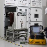
Automated RMUs need coordinated protection, reliable position feedback, communications, and a defined local operating procedure.
Protection sequence during a fault
A fault causes current and voltage conditions detected by the applicable protection.
The designated breaker or fuse interrupts fault current within its rating.
Operators or automation identify the affected section using relay records, fault indicators, and network information.
The faulted cable is isolated at both ends and earthed under the switching procedure.
Healthy sections are assessed for alternative supply capacity and protection coordination.
The network open point is changed to restore eligible loads.
The faulted section remains secured until repaired, tested, and formally returned to service.
The exact sequence varies. Some simple RMUs have no remote control; advanced units may include motor operators, fault-passage indicators, voltage sensors, RTUs, SCADA, and automated restoration. Automation must fail safely and preserve local control and interlocking.
Normally open versus closed-ring operation
An open ring is operationally radial and often simplifies protection while preserving an alternate physical path. A closed ring can provide continuous supply from both directions but requires protection capable of detecting fault direction and isolating the correct section. Fault level, power flow, source synchronization, relay communications, and utility policy determine whether closed operation is permitted.
Do not close a normally open point simply because the equipment ratings appear adequate. Confirm source phase relationship, voltage difference, fault duty, cable capacity, earthing arrangement, and protection study.
Specification inputs buyers must provide
System voltage, frequency, maximum operating voltage, and earthing method.
Rated current, short-time withstand, peak withstand, and fault-interruption duty.
Number and function of ways, cable sizes, entry direction, terminations, and test points.
Transformer rating and protection philosophy for the tee-off way.
Indoor/outdoor environment, altitude, temperature, humidity, pollution, and enclosure protection.
Manual or motor operation, auxiliary supply, indications, RTU, protocol, and cybersecurity requirements.
Applicable standard, utility approval, routine/type-test documentation, and site commissioning scope.
Common misunderstandings
An RMU is not necessarily operated in a permanently closed electrical ring.
“Gas insulated” does not describe every RMU, and insulation medium does not determine the full performance rating.
A load-break switch is not automatically a fault-interrupting circuit breaker.
An earthing switch is a controlled safety device, not permission to skip absence-of-voltage verification.
Remote automation does not eliminate local interlocks, maintenance, or switching procedures.
Compact size does not remove cable bending, pressure relief, access, or foundation requirements.
Example restoration decision
Suppose a fault indicator operates on the cable leaving station B toward station C. That indication narrows the search but does not prove the exact faulted segment. The control center reviews protection records and the network diagram, then authorized operators isolate the suspected cable at both ends. They prove the isolated section, apply earths, and verify that the remaining path can carry transferred load.
Before closing the alternate supply, the engineer checks source compatibility, cable and switch ratings, voltage conditions, and protection direction. Healthy stations can then be restored while the failed cable stays isolated. After repair, the cable is tested and the network returns to its approved normal open point. The RMU enables restoration, but protection evidence, switching authority, ratings, and verification make it safe.
Educational video: radial and ring network operation
This independent educational explanation visualizes how an RMU supports radial and ring distribution. Always use the approved project single-line diagram for operations.
Operating boundary: No switching step should be inferred from this conceptual example. The authorized switching program must identify the exact devices, normal positions, isolation points, voltage checks, earths, interlocks, load-transfer limits, communications, and hold points. Network diagrams must reflect current field configuration; an outdated mimic or SCADA display can turn an otherwise reasonable sequence into the wrong operation.
Before remote control is enabled, test command authority, position feedback, interlocks, loss-of-communications behavior, local takeover, time synchronization, alarms, and event records. Operators should know how automation is blocked during maintenance and how the network behaves after auxiliary-power failure. These functional details determine whether a “smart RMU” improves restoration or merely adds unverified control paths.
Ring main unit working principle FAQ
Is an RMU always a closed ring?
No. Many networks use an open ring: physically looped but operated radially with one normally open point.
Can an RMU interrupt a short circuit?
The answer depends on the way. A circuit breaker or fuse interrupts specified faults; a load-break switch alone has different duties.
Why are there usually three ways?
Two ways continue the incoming and outgoing ring, while the third supplies and protects a transformer or feeder.
Does an RMU restore supply automatically?
Only when sensors, motor operators, protection, communications, control logic, and an approved automation scheme are provided.
What is the purpose of the earthing switch?
It connects an isolated circuit to earth within a controlled safety procedure and must be coordinated with position verification and interlocks.

 شركة شنغهنغ لعدات الطاقة المحدودة.